Language
Content
Press brake sheet metal bending delivers accurate, repeatable bends when you apply four proven rules: set the V-die opening to roughly eight times the material thickness, use air bending as the default process, calculate tonnage with one formula, and compensate for springback before you release the first part. Fabricators who skip these basic decisions deal with cracked flanges, angle drift, overload alarms, and scrapped blanks. Fabricators who apply them hold angular consistency within +/-0.5 degree and back-gauge positioning to +/-0.02 mm on modern CNC equipment.
This guide covers press brake types, the bending sequence step by step, the bend allowance and tonnage formulas, die and punch selection, material limits, precision control, maintenance planning, and the point at which a sheet metal shop should add CNC wire bending capacity. The final section answers the most common questions that buyers and operators ask.
A press brake clamps a flat metal sheet between an upper punch and a lower V-die, then drives the punch downward with controlled force or position until the sheet deforms plastically to the target angle. A back gauge moves the sheet to the exact bend line before every stroke, and the CNC controller synchronizes ram travel, die contact, and gauge positioning. What defines a successful bend is not hitting the angle once, but repeating the same angle on every part in the batch.
Four decisions determine most of the result: machine type, tooling, material condition, and bending process.
Buyers today choose between four main drive technologies. Mechanical press brakes use a flywheel and often lack full positional control; they survive in old shops for simple, repetitive work. CNC hydraulic machines are the standard for medium and heavy fabrication because they combine high tonnage with good stroke control. Servo-electric machines drive the ram with servo motors and ball screws, eliminating hydraulics and cutting energy use. CNC hybrid systems add adaptive angle measurement and automatic crowning for demanding parts.
| Type | Usual tonnage range | Ram repeatability | Energy behavior | Best fit |
|---|---|---|---|---|
| Mechanical | 30-400 US tons | +/-0.05 mm | Flywheel, continuous running | Long-run simple bends |
| Hydraulic CNC | 40-2,000+ tons | +/-0.02 mm | Pump runs continuously | Heavy plate, long parts, variable stroke |
| Servo-electric | 20-220 tons | +/-0.01 mm | Motor on demand, about 50% energy saving | Thin and medium gauges, clean shops, high cycle rates |
| CNC hybrid / adaptive | 60-500 tons | +/-0.01 mm | Hybrid drive, moderate consumption | Complex parts, adaptive angle control, low tool wear |
For shops bending sheet metal thinner than 3 mm in medium batches, a servo-electric unit offers the best accuracy per euro. For thick plate, long bend lines, or deep boxes, a CNC hydraulic machine remains the practical choice because it can apply high tonnage at any point of the stroke.
A disciplined sequence removes most quality problems before they appear. Shops that follow a written procedure reduce first-part scrap and keep setup time predictable.
The flat blank length equals the two straight flange lengths plus the bend allowance. The bend allowance is the arc length measured along the neutral axis of the sheet. The neutral axis sits closer to the inner surface on sharp bends, which is why the K-factor appears in the calculation.
BA = (pi / 180) x bend angle x (inside radius + K-factor x material thickness)
For a 90-degree bend in 2 mm mild steel with a 2 mm inside radius and a K-factor of 0.44, the allowance is 1.5708 x (2 + 0.88) = 4.52 mm. That small number shifts the flat blank size and can turn an otherwise good part into a short flange if ignored.
| Material or bending condition | Typical K-factor |
|---|---|
| Soft copper, annealed aluminum, very soft tempers | 0.45-0.50 |
| Cold-rolled mild steel | 0.40-0.44 |
| Stainless steel 304 | 0.40-0.44 |
| Hard aluminum such as 6061-T6 | 0.33-0.40 |
| Large radius where radius is more than five times thickness | Approaches 0.50 |
Every metal springs back after the punch lifts. The springback angle is the gap between the bent angle and the programmed angle. The standard fix is to overbend slightly, which works well for mild steel, or to switch from air bending to bottoming, which presses the sheet fully into the die and mechanically reduces elastic recovery.
| Material | Springback range | Practical note |
|---|---|---|
| Mild steel | 1-3 degrees | Can usually be corrected by overbending in the program |
| Stainless steel 304 | 5-10 degrees | Work-hardened stainless springs back more; bottoming helps |
| Aluminum 5052-H32 | 2-4 degrees | Low variation within a lot |
| Aluminum 6061-T6 | 1-3 degrees | Sharp radii may crack before springback matters |
| High-strength steel 780 MPa | 8-15 degrees | Use adaptive angle measurement if available |
Tooling is where press brake sheet metal quality is won or lost. A worn punch tip creates a visible line on every part. A die that is too narrow for the material cracks the outer surface. A gooseneck punch is required when a flange must clear the tool after bending. The single most useful rule for die selection is the V-opening rule: divide the V-opening by the material thickness. The ratio should sit between 6 and 12, with 8 as the default for mild steel.
| Parameter | Air bending | Bottoming | Coining |
|---|---|---|---|
| Tool contact | Three points only | Sheet pressed into the die | Full squeeze below sheet surface |
| Relative tonnage | 1x baseline | Roughly 3-4x air bending | 5-10x air bending |
| Angle accuracy | +/-0.5 degree typically | +/-0.25 degree with uniform material | Very high, limited by machine stiffness |
| Sensitivity to thickness variation | Low to medium | High | Medium |
| Typical use | General fabrication, default choice | Parts needing a sharp inner corner | Micro bends, thin stock, precise angles |
The industry-standard formula for air bending mild steel relates force to material thickness and die opening. The formula below gives kilonewtons per meter of bend length for steel with a tensile strength near 450 MPa.
P (kN per meter) = 650 x (thickness in mm) x (thickness in mm) / (V-opening in mm)
To convert to metric tons of force, divide the result by 9.81. For 3 mm mild steel over a 24 mm die, the calculation is 650 x 9 / 24 = 243.75 kN per meter, or about 24.8 tons per meter. A part with a 1.2 m flange needs 292.5 kN, roughly 29.8 tons, before any safety factor. Buying a machine rated at 30 tons leaves no headroom; a 40-ton model is the realistic choice.
| Thickness (mm) | Recommended V-opening (mm) | Force (kN/m) | Force (tons/m) |
|---|---|---|---|
| 1.0 | 8 | 81.3 | 8.3 |
| 1.5 | 12 | 121.9 | 12.4 |
| 2.0 | 16 | 162.5 | 16.6 |
| 3.0 | 24 | 243.8 | 24.9 |
| 4.0 | 32 | 325.0 | 33.1 |
| 5.0 | 40 | 406.3 | 41.4 |
For stainless steel, multiply the result by 1.4 to 1.6. For 5xxx aluminum, multiply by 0.7 to 0.8. For 780 MPa high-strength steel, multiply by 1.7 to 2.2. These factors reflect the difference in tensile strength compared with mild steel.
Each material has a floor below which it will crack on the bend line. The table gives air-bending minimums for common grades. These are starting points: a sharper punch tip, a smaller V-opening, or bending parallel to the grain all raise the practical minimum radius.
| Material | Minimum inside radius (air bending) | Tonnage factor vs mild steel | Key caution |
|---|---|---|---|
| Cold-rolled mild steel | 0.5-1.0 x T | 1.0 | Bend across the grain for visible flanges |
| Stainless steel 304 | 1.5-2.0 x T | 1.4-1.5 | Work-hardened sheets need a larger radius |
| Aluminum 5052-H32 | 0.5-1.0 x T | 0.7 | Good formability in H32 temper |
| Aluminum 6061-T6 | 2.0-3.0 x T | 0.7 | Sharp radii cause cracking; consider O-temper for hard form |
| High-strength steel 780 | 2.0-3.0 x T | 1.7-2.2 | High springback and edge micro-cracks possible |
Material thickness tolerance also creates angle variation. In air bending, a sheet that is 0.1 mm thicker than nominal can shift the angle by one degree or more because the punch depth that worked for nominal thickness now forms a different angle. This is why adaptive control with angle feedback is becoming common in precision press brake sheet metal work.
A press brake is only as precise as its positioning system. The back gauge controls the distance from the bend line to the reference edge, and its repeatability directly affects flange length. Basic machines have a two-axis gauge; production machines add an R-axis for gauge height and Z-axis stops for different part widths. A 4+1-axis back gauge is the practical minimum for job-shop flexibility.
For high-precision work, keep the tooling parallel with the ram. Even a 0.1 mm mismatch between punch and die across a 2 m length will produce a tilted angle. Use precision-ground dies and check parallelism when installing new tooling.
Press brakes support nearly every metal-product industry because they produce simple, strong, cost-effective shapes from flat sheet. The fabrication list is long, and each sector adds its own tolerances and surface requirements.
For mobility and automotive applications, the trend toward electric vehicles has increased demand for precise, high-strength steel bends because battery housings and structural brackets replace parts that were welded before.
Most press brake failures are not sudden; they show up first as angle drift, scratches, or unusual noise. A simple fault register helps identify the source quickly.
| Fault | Likely cause | Practical fix |
|---|---|---|
| Inconsistent angle across a batch | Material thickness shifts, springback not compensated | Use depth-controlled air bending; measure the first part from each new lot |
| Cracks on the outer bend line | Radius too small, grain parallel to the bend | Increase punch radius; rotate blank 90 degrees; test softer temper |
| Twisted or warped part | Punch and die not parallel, back gauge ends misaligned | Check ram/die parallelism; verify both gauge fingers touch the sheet |
| Scratches on the underside | Burr on the die edge, dirty tooling, hard particles | Stone and clean the die; deburr blanks; apply protective film |
| Overload alarm on the controller | V-opening too narrow or tonnage underestimated | Recalculate with the 650 formula; move to a wider die |
Fabrication shops that bend sheet metal often receive requests for wire-formed parts: clips, hooks, pins, and wire brackets that belong to the same product assembly. Press brakes cannot bend wire profiles efficiently, but CNC wire bending machines process round wire, flat wire, and strip with the same programmed precision. A CNC wire bender straightens, feeds, bends, and cuts the wire in one sequence, which makes small to medium wire batches profitable.
The control logic of a wire bender has much in common with a press brake: you program bend angles, feed lengths, and springback compensation. Multi-axis machines such as the ZW-480 add a twist axis and a bending arm that allow complex three-dimensional shapes. For a deeper explanation of the bending kinematics, read our full guide on how bending machines work.
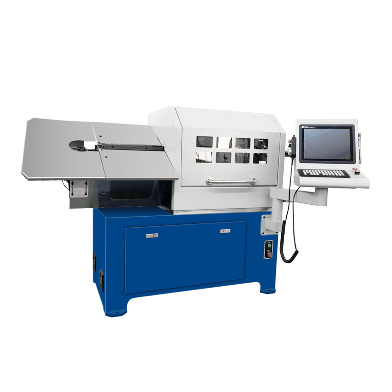 ZW-480 4-Axis CNC Spring Wire Bending Machine for Complex 3D ShapesThis four-axis wire bender supports twist and bending arm movements for intricate three-dimensional forms. It offers unattended operation and is economical for small to medium batch production.View Product →
 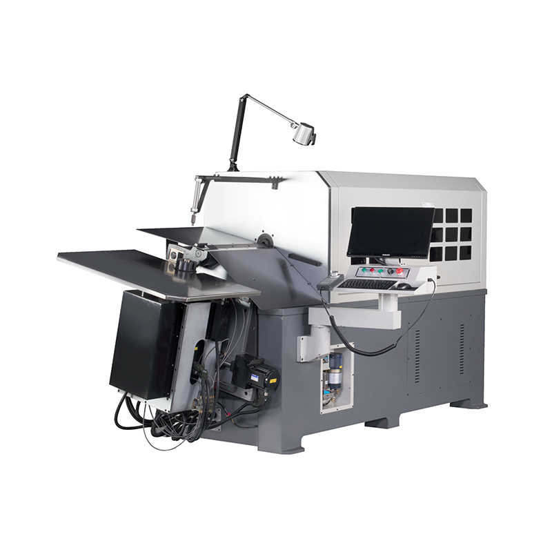 ZW-880 8-Axis CNC Spring Wire Bending Machine for High-Precision WorkWith eight-axis linkage and rotary wire feed, this model provides high stability and precision. It can handle complex forming tasks and is ideal for job shops looking to produce complete assemblies.View Product →
 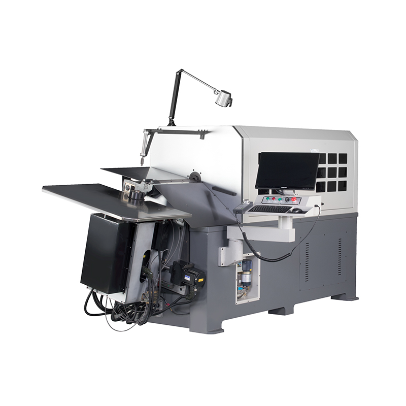 WNJ CNC Wire Bending Machine Series (1–12mm Wire Diameter)This manufacturer’s line covers wire diameters from 1 to 12 mm with multi-axis linkage. It includes global support and spare parts services, making it a reliable choice for production integration.View Product →
Adding a wire bending line next to a press brake lets a job shop quote complete assemblies instead of individual parts. The setup cost is low, and the machines run unattended enough to be economical for batches of a few hundred pieces.
Air bending forms the sheet with contact at only three points: the two die edges and the punch nose. The angle depends on punch depth, so one tool can make many angles. Bottoming presses the sheet fully into the V-die, which reduces springback and sharpens the inside corner but increases tonnage three to four times. Coining compresses the material so much that the punch shape is pressed into the sheet; it needs the highest tonnage and delivers the best repeatability for thin material. For most press brake sheet metal work, air bending is the correct default.
Start with the rule of eight: for mild steel, use a V-opening equal to eight times the material thickness. Move to ten to twelve times for stainless steel, and six to eight times for soft aluminum. A wider die reduces tonnage and produces a larger inside radius; a narrower die increases tonnage and sharpens the radius. The V-opening must never be smaller than five times the thickness for standard materials.
The simplest method is to program an overbend angle equal to the measured springback. Use a test piece from the exact coil you will run in production. For high-springback materials such as stainless or 780 MPa steel, switch to bottoming or use a press brake with adaptive angle measurement, which corrects the punch depth automatically after the first test bend.
Use the formula P = 650 x 9 / 24 = 243.75 kN per meter, which is roughly 24.8 tons per meter. Add a safety factor and avoid running over 80% of rated capacity, so a 40-ton press brake is the minimum sensible choice for one-meter bends in 3 mm mild steel. Increase the machine size if you also bend stainless or high-strength steel.
Cracks form when the outside surface reaches its elongation limit. Common causes are a punch radius below 1.5 times the material thickness, bending parallel to the rolling grain, work-hardened sheet from a prior forming step, or a V-die that is too narrow. Use a larger radius, bend across the grain, and confirm with a bend test on scrap before production.
Servo-electric machines suit sheet metal up to about 3 mm, with cleaner operation, lower energy cost, and better positioning repeatability. CNC hydraulic machines remain superior for thick plate, deep parts, and long bend lines because they generate high tonnage across the whole stroke. Choose servo-electric for precision light-gauge work and hydraulic CNC for general fabrication with a wide material range.
Press brake sheet metal bending is a mature process, and the technology has not changed in its fundamentals. What separates profitable shops is discipline: correct die selection, honest tonnage calculation, tested springback compensation, and regular tooling maintenance. Apply these practices consistently, and the press brake becomes one of the most predictable machines on the floor.
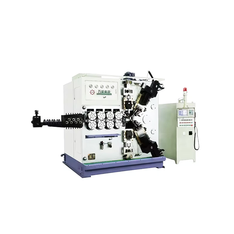
TK-6160 TK-6160 CNC SPRING ROLLING MACHINE...
See Details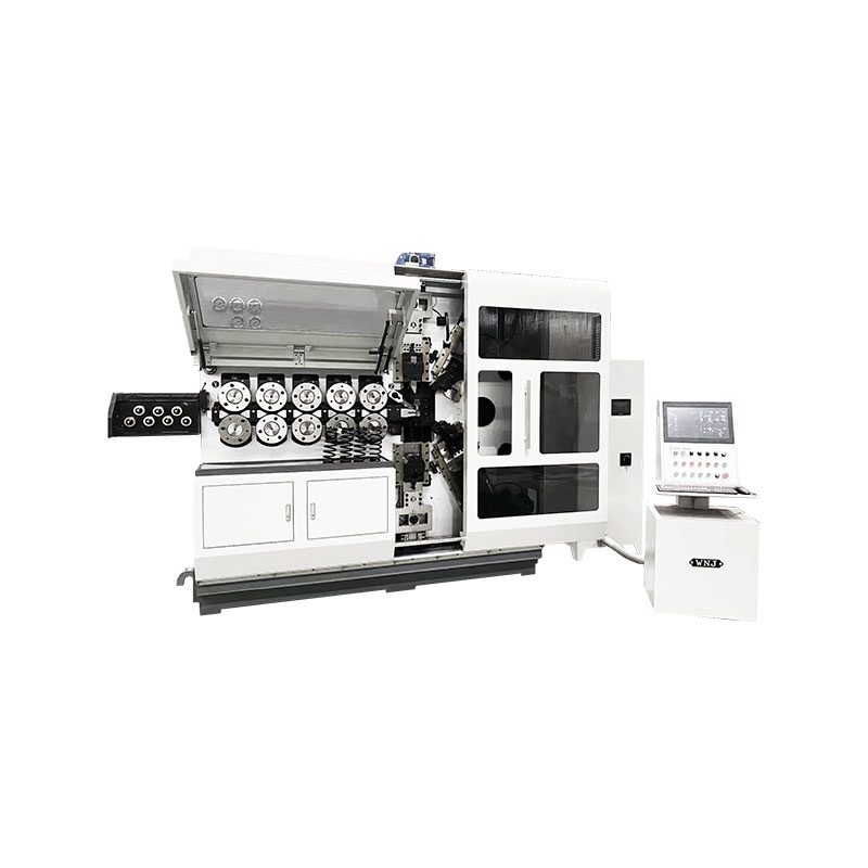
TK-6120 TK-6120 CNC SPRING ROLLING MACHINE...
See Details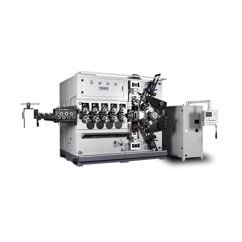
TK-5200 TK-5200 5AXES CNC SPRING COILING MACHINE...
See Details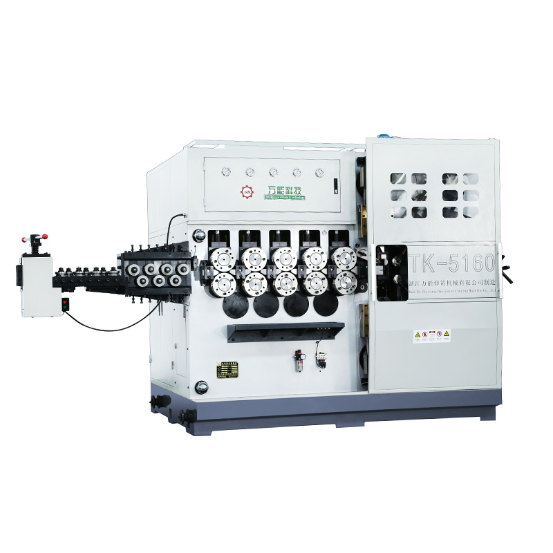
TK-5160 TK-5160 5AXES CNC SPRING COILING MACHINE...
See Details
TK-5120 TK-5120 5AXES CNC SPRING COILING MACHINE...
See Details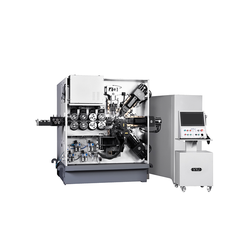
TK TK 10AXES CNC SPRING SCROLL MACHINE...
See Details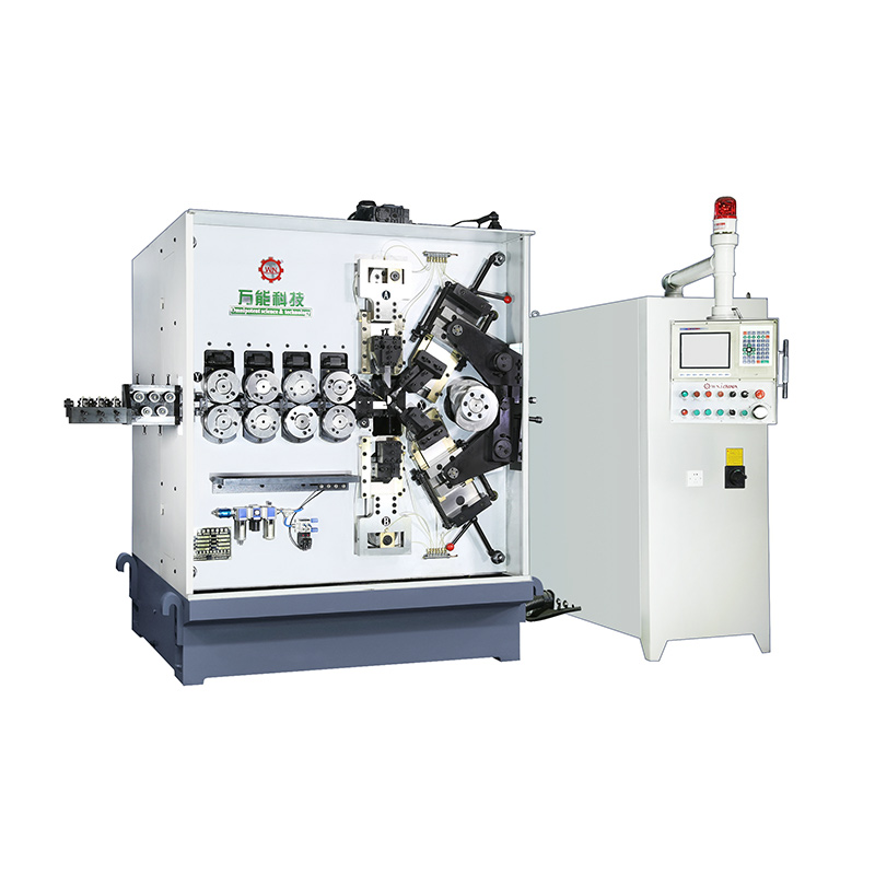
TK-580B、 TK-590 TK-580B、 TK-590 5AXES CNC SPRING COILING MACHINE...
See Details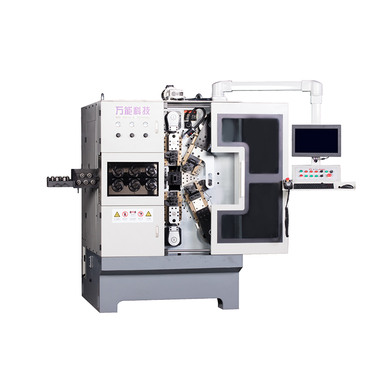
TK-760TK-760 6-7AXES CNC SPRING COILING MACHINE...
See DetailsMobile QR Code

 中文简体
中文简体 English
 русский
 Español