Content
A bending machine works by applying a controlled force to a workpiece — typically metal, wire, or tube — to deform it into a specific angle or shape without cutting or welding. The machine uses a combination of a punch (upper die), a die (lower die), and a back gauge to position and bend the material with repeatable accuracy. The fundamental mechanics rely on exceeding the material's yield strength so it permanently deforms, while staying below its tensile strength to avoid fracture.
In practical terms, when the punch descends into the die, it forces the sheet metal or wire to conform to the die geometry. The angle achieved depends on the penetration depth, the die opening width, and the material's own springback characteristics. Modern CNC bending machines control all these variables digitally, enabling tolerances as tight as ±0.1° on bend angle and ±0.1 mm on back gauge positioning.
There are several primary bending methods in industrial use, each suited to different materials and production volumes:
Understanding what each part does helps operators troubleshoot problems and optimize output quality. Every bending machine, regardless of type, shares a common set of mechanical and control components.
The machine frame is a welded or cast steel structure that absorbs bending forces without deflecting. On large press brakes rated at 400 tons or more, the bed deflects measurably under load — sometimes 0.3–0.5 mm across a 4-meter span. Better machines use crowning systems (mechanical or hydraulic wedge-based) to compensate for this deflection and maintain angle consistency across the full part length.
The ram carries the upper tooling (punch) and is driven downward by hydraulic cylinders, servo-electric drives, or mechanical eccentrics. Servo-electric press brakes, now standard in precision sheet metal shops, achieve positioning repeatability of ±0.01 mm — significantly better than conventional hydraulic designs, which typically achieve ±0.04 mm.
The punch tip radius, die opening width (V-opening), and die shoulder radius all directly affect bend quality. A standard rule is that the V-opening should be 6–10 times the material thickness. For example, bending 3 mm mild steel typically uses a 20–24 mm V-die. Using too narrow a die causes excessive material thinning and cracking; too wide a die increases springback and reduces angle accuracy.
The back gauge is a motorized stop that positions the material precisely before each bend. Modern multi-axis back gauges (typically 4–6 axes) allow CNC control of both depth and height, enabling complex flanged parts to be produced automatically without manual repositioning. Back gauge accuracy directly determines the flange length tolerance, which on well-maintained CNC press brakes runs ±0.1 to ±0.2 mm.
Modern bending machines run dedicated CNC controllers (Delem, Cybelec, or proprietary systems) that store bend programs, calculate required tonnage, compensate for springback, and coordinate multi-axis motion. Offline programming through CAD/CAM software (e.g., Radan, SolidWorks Bend) allows engineers to develop bend sequences on a computer and transfer them directly to the machine, reducing setup time by 40–70% compared to manual trial-and-error programming.
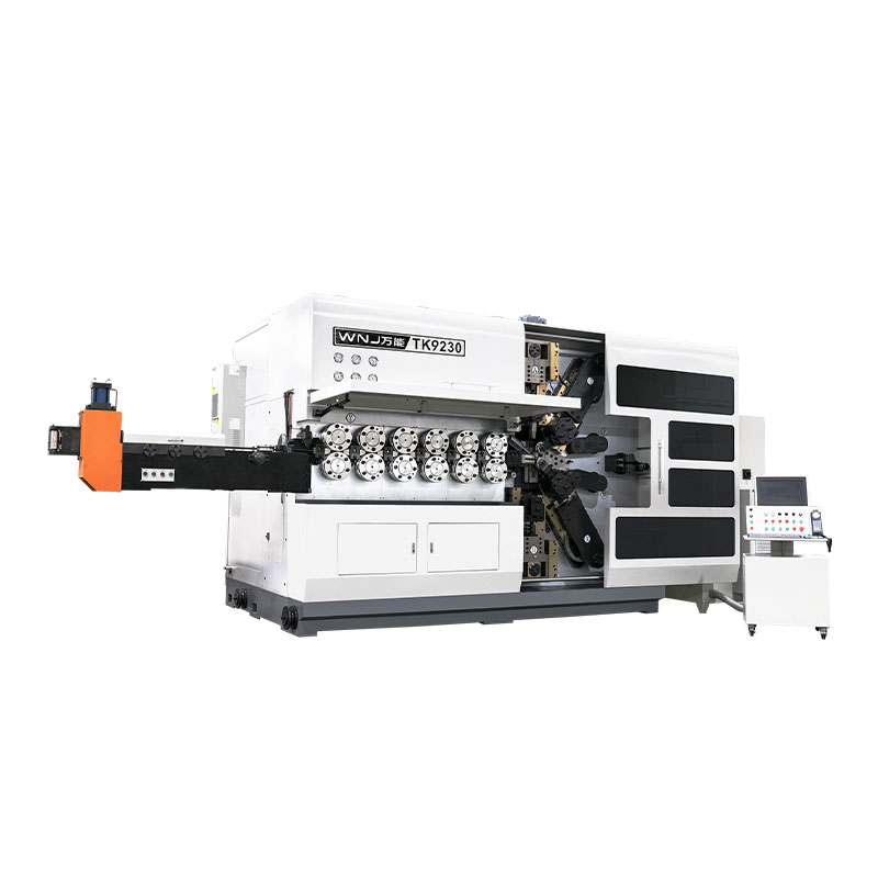
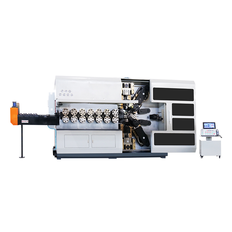
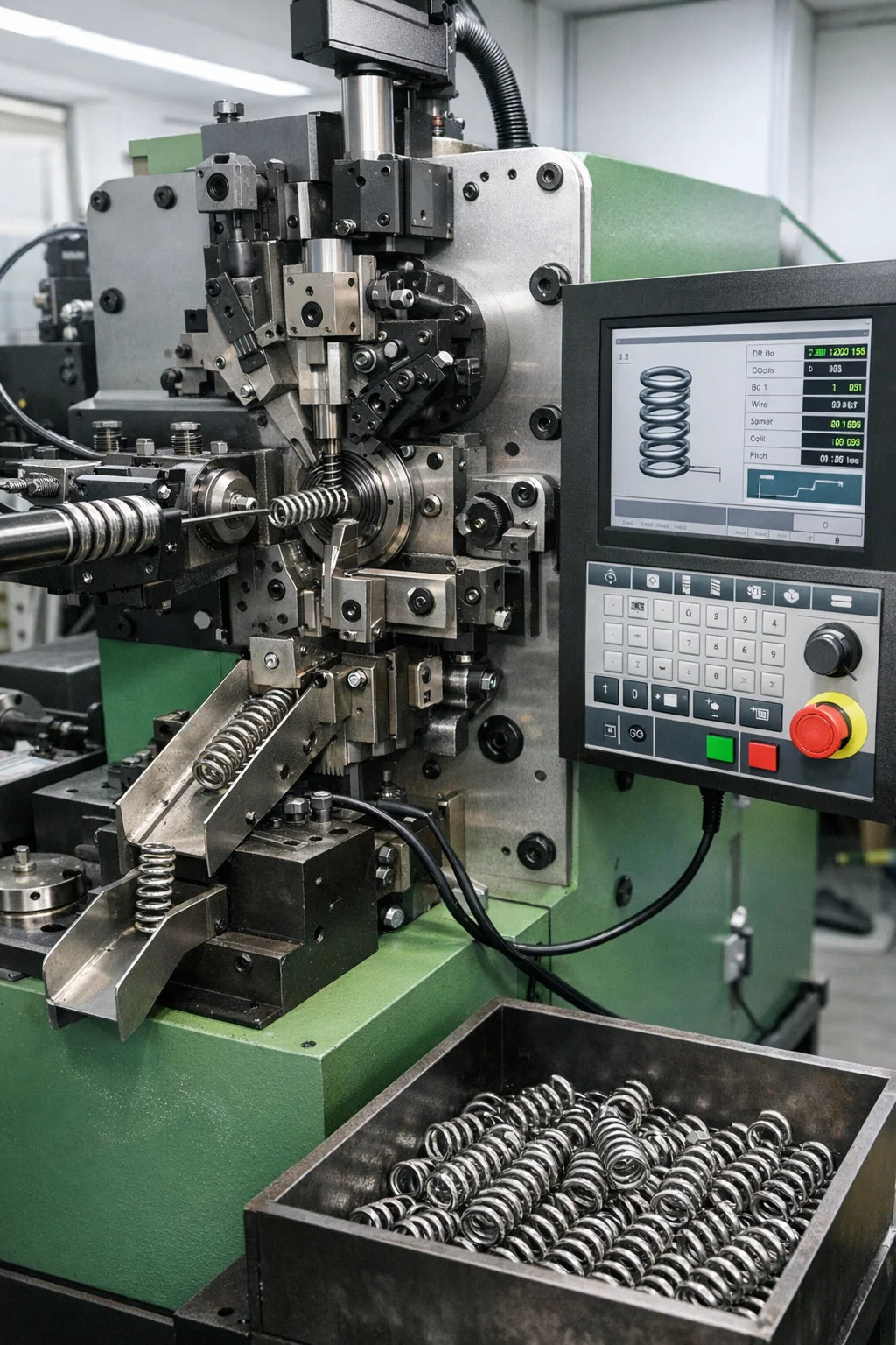
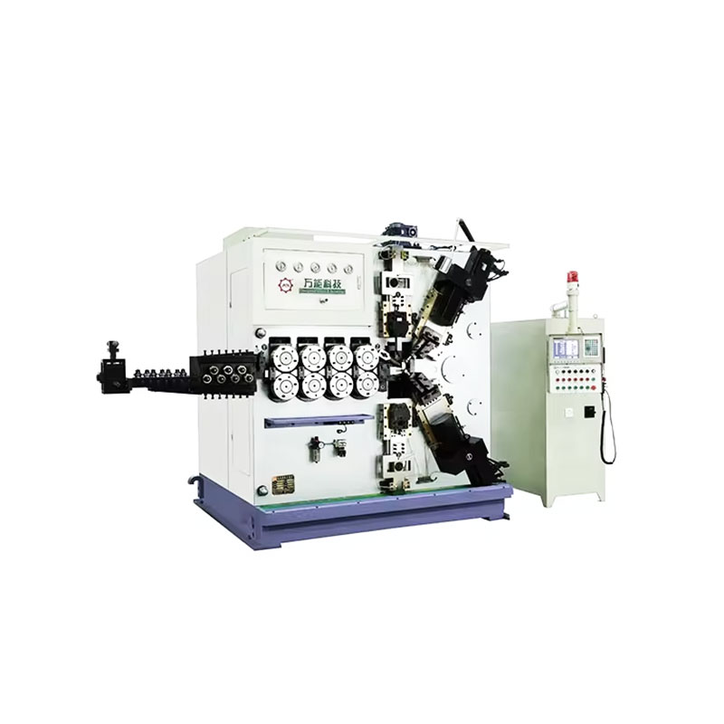
A spring bending machine is a specialized type of bending machine designed specifically to form wire or flat stock into springs and spring-like shapes — including coils, torsion springs, compression springs, extension springs, and custom wire forms. Unlike standard sheet metal press brakes, a spring bending machine operates with rotating bending pins, adjustable cams, and a wire-feed mechanism that work together to continuously shape wire as it is fed through the machine.
The fundamental working cycle of a CNC spring bending machine goes through the following stages:
High-speed CNC spring bending machines typically produce 30–200 springs per minute depending on wire diameter and spring complexity. Some high-volume coilers running thin wire (0.1–0.5 mm) in the electronics sector exceed 400 parts per minute.
Spring bending machines come in several configurations depending on the spring type and production requirements:
| Machine Type | Wire Diameter Range | Typical Application | Production Speed |
|---|---|---|---|
| Compression spring coiler | 0.1 – 20 mm | Automotive suspensions, industrial valves | 30 – 200 pcs/min |
| Extension spring coiler | 0.2 – 12 mm | Door hinges, retractable mechanisms | 20 – 150 pcs/min |
| Torsion spring bending machine | 0.3 – 10 mm | Clothespins, electrical contacts, clamps | 15 – 80 pcs/min |
| CNC wire forming machine | 0.5 – 16 mm | Custom wire shapes, hooks, brackets | 5 – 60 pcs/min |
| Flat spring bending machine | Strip 0.1 – 3 mm thick | Battery contacts, snap-fit terminals | 20 – 120 pcs/min |
Springback is one of the most significant challenges in any bending operation, whether on a sheet metal press brake or a spring bending machine. When a force bends metal, only part of the deformation is plastic (permanent). The elastic portion recovers once the force is released, causing the part to spring back toward its original shape. For common mild steel sheet, springback angles typically range from 1° to 5°, while high-strength steels and stainless steel can spring back 6°–12° or more.
Spring bending machines face an especially acute version of this problem. The entire product is defined by its elastic recovery — a compression spring, for example, must store and release energy predictably, so the coiling process must account for springback precisely to achieve the target free length and spring rate. A spring that springs back more than programmed will be too long; one that springs back less will be too short, and both will fail load testing.
The distinction between CNC-controlled and manual bending machines goes far beyond price. Each has a specific operating context where it delivers the best return.
| Criteria | CNC Bending Machine | Manual Bending Machine |
|---|---|---|
| Angle repeatability | ±0.1° – ±0.3° | ±1° – ±3° (operator-dependent) |
| Setup time | 5–20 minutes (program recall) | 30–90 minutes (manual adjustment) |
| Suitable batch size | 1 – 100,000+ | 1 – 500 (low-volume custom work) |
| Operator skill required | Moderate (CNC programming) | High (experienced bender) |
| Initial machine cost | $30,000 – $500,000+ | $1,000 – $30,000 |
| Complex geometries | Excellent (multi-axis automation) | Limited |
For spring bending machines specifically, CNC systems dominate medium-to-high volume production because wire form geometry is almost impossible to replicate consistently with manual pin adjustments when run rates exceed 50 parts per minute. Manual spring bending machines remain viable for prototype work, specialty repair shops, and very small batches of large-diameter wire springs where machine setup time dwarfs actual production time.
Bending machines are not material-agnostic. Each material class responds differently to bending forces, and machine parameters must be adapted accordingly.
Selecting the wrong machine is an expensive mistake. The right bending machine depends on at least six converging factors, and each must be evaluated together rather than in isolation.
For sheet metal, the required tonnage scales with material yield strength and thickness squared. Doubling material thickness roughly quadruples required tonnage. A shop that primarily bends 3 mm mild steel up to 2,500 mm wide needs approximately 100–160 tons of press brake capacity. If they later need to bend 6 mm stainless, that same part could require 400+ tons — far exceeding the machine's rating.
For spring work, the wire diameter range drives machine selection almost exclusively. A spring bending machine designed for 0.5–4 mm wire cannot reliably process 8 mm wire without risking motor overload and tool breakage.
Simple 2D bends on flat sheet can be handled by any press brake. Parts with complex flange relationships, hem bends, or negative angles require off-center tooling, special die configurations, or robotic part manipulation. For wire forms with 3D geometry — hooks, loops, and multi-plane bends — only a multi-axis CNC wire forming machine with 6 or more independently controlled axes can handle production-volume output.
A shop producing 50 custom brackets per week has no justification for a $200,000 CNC press brake with automatic tool changer. Conversely, a spring manufacturer running 500,000 compression springs per month cannot rely on a semi-automatic coiler — cycle time and tooling wear will make costs unsustainable. Break-even analysis consistently shows that CNC spring bending machines pay back their investment within 12–24 months at production rates above 50,000 parts per month compared to manual or semi-automatic alternatives.
Aerospace and medical parts routinely require bend angles held to ±0.25° and flange lengths to ±0.1 mm. Achieving this reliably on a hydraulic press brake without angle measurement feedback is nearly impossible across a full production run. For spring bending, free-length tolerances of ±0.3 mm on a 50 mm spring body demand a machine with stable wire feed resolution and consistent springback compensation — typically achievable only with servo-driven CNC coilers.
Even well-configured machines produce defective parts when variables are not controlled. The following problems are the most frequently reported across both press brake and spring bending machine operations.
If the bend angle is correct at the center but opens up toward the ends, the machine bed is deflecting under load. A 3-meter bend on a 250-ton press brake without active crowning can show 0.4–0.8 mm of deflection at the center relative to the ends, translating to 1°–2° of angle variation. The fix is a hydraulic or mechanical crowning table or shorter tooling segments that allow per-section adjustment.
Cracking occurs when the outer fiber strain exceeds the material's elongation capacity. Common causes include using a punch radius smaller than the minimum recommended for the material (for 6061-T6 aluminum, minimum inside radius is typically 1.5–2× material thickness), bending across the grain direction of rolled sheet, or using work-hardened material from previous forming operations. Rotating the part 90° relative to rolling direction often eliminates cracking on borderline materials.
Free-length scatter in production springs (e.g., ±1 mm on a target of ±0.3 mm) usually traces back to one of three causes: wire diameter variation between coils exceeding the tolerance the machine was calibrated for, temperature-driven changes in material hardness on long production runs, or worn feed rollers that slip intermittently. Replacing feed roller inserts every 300–500 operating hours is standard preventive maintenance in high-volume spring shops.
Twist develops when residual stress in the wire coil is not released uniformly as the wire feeds through the machine. A wire straightener (rotary or roller-type) mounted between the wire spool and the feed rollers removes the coil set before forming. Most production spring bending machine setups include a 7- or 9-roller straightener as standard equipment.
Bending machines — particularly hydraulic press brakes rated at 100 tons or more — generate forces capable of crushing hands and causing fatal injuries. Safety standards are not optional in any professional operating environment.
A well-maintained bending machine should provide 20–30 years of productive service. Neglected machines deteriorate rapidly, producing out-of-tolerance parts and creating safety hazards. The following maintenance practices are non-negotiable in production environments.
Tooling is typically the highest recurring maintenance cost in both press brake and spring bending machine operations. Punch tips wear and nick; die shoulders erode from repeated metal contact. A single set of precision press brake tooling for a 3-meter machine can cost $3,000–$15,000, making proper storage (tool racks, protective covers) and handling procedures a direct cost control measure.
TK-6160 TK-6160 CNC SPRING ROLLING MACHINE...
See Details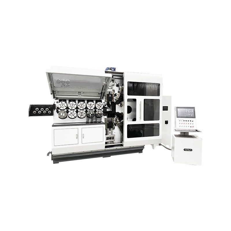
TK-6120 TK-6120 CNC SPRING ROLLING MACHINE...
See Details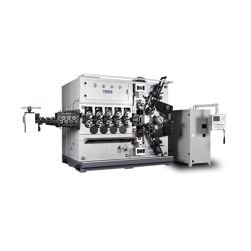
TK-5200 TK-5200 5AXES CNC SPRING COILING MACHINE...
See Details
TK-5160 TK-5160 5AXES CNC SPRING COILING MACHINE...
See Details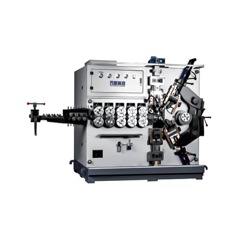
TK-5120 TK-5120 5AXES CNC SPRING COILING MACHINE...
See Details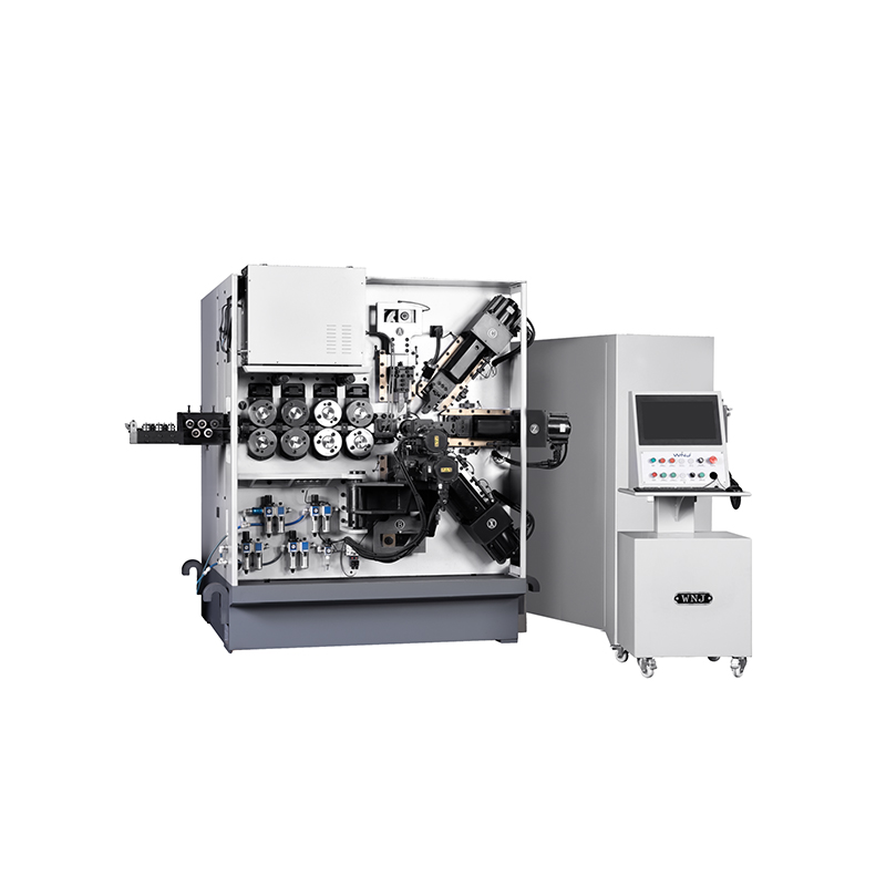
TK TK 10AXES CNC SPRING SCROLL MACHINE...
See Details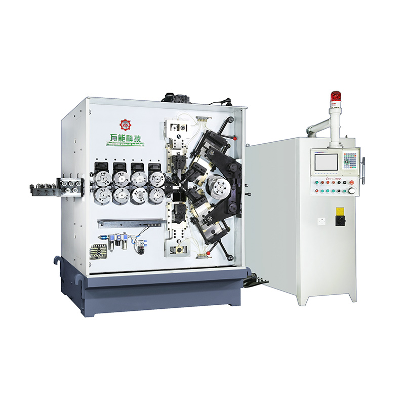
TK-580B、 TK-590 TK-580B、 TK-590 5AXES CNC SPRING COILING MACHINE...
See Details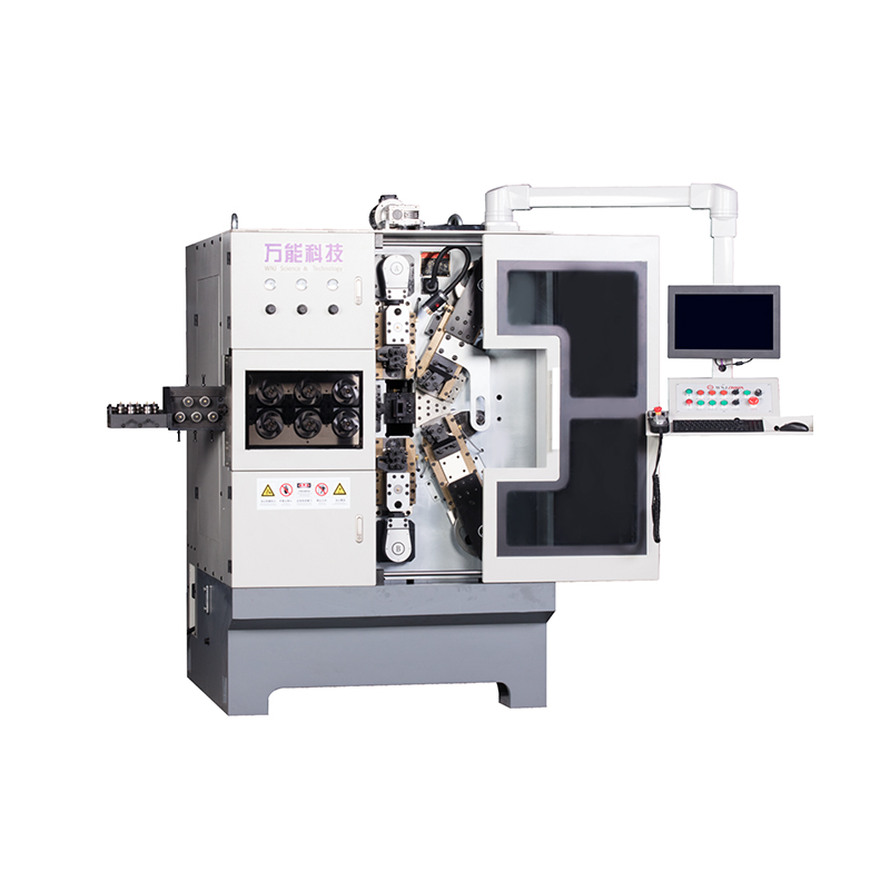
TK-760TK-760 6-7AXES CNC SPRING COILING MACHINE...
See DetailsMobile QR Code

 Language
  中文简体
中文简体 English
 русский
 Español