Language

Content
Bending a wire is a controlled plastic deformation, and it only works when you manage three variables at the same time: support, bend radius and springback. Support the wire on both sides of the bend so the deformation happens exactly where you want it. Keep the inside radius above the minimum the material can tolerate. Then overbend by a measured amount so the wire springs back to the angle you actually need. A 1 mm annealed copper wire will follow your fingers. A 5 mm oil-tempered spring steel rod will crack on the outside of a tight bend unless the radius, the temper and the bend direction are planned before any tool touches it.
This guide covers the mechanics behind a bend, the radius figures that matter, a repeatable hand-bending method, how common wire materials behave, and the point where a manual bender stops being practical and a CNC wire bending machine takes over. Every number here is a starting point for a test bend, not a substitute for one.
When a wire bends, the outside of the curve stretches and the inside compresses. The middle layer, called the neutral axis, keeps its original length. The number that decides whether the bend survives is the strain on the outer surface, and it is quick to calculate:
Surface strain = d / (2R + d), where d is the wire diameter and R is the inside bend radius.
Those three results explain most cracked bends in a shop: too much stretch, on too small a radius, in a material that has almost no ductility left. Pull the allowable bending strain from the wire supplier's data sheet and compare it with the calculated figure before you commit a batch. Every bend also work-hardens the wire at that spot, so a wire that bends cleanly once may snap if you open it and close it repeatedly at the same point.
Minimum bend radius is normally written as a multiple of the wire diameter, because a 1 mm wire and a 6 mm wire made from the same alloy do not share the same absolute radius limit. The table below lists typical starting values used in wire forming and spring making. Harder tempers push the number up; preheating or annealing pulls it down.
| Wire material | Minimum inside radius | Practical note |
|---|---|---|
| Annealed copper, brass | 0.5d to 1d | Very forgiving, low springback |
| Mild steel, annealed | 1d to 2d | Watch for orange peel on thick stock |
| Stainless 304, 316 annealed | 1d to 2d | Work hardens quickly, bend once |
| Phosphor bronze, spring temper | 3d to 4d | Moderate springback, clean edges |
| Music wire, oil-tempered spring steel | 4d to 6d | High tensile, high springback |
If a design needs a radius tighter than the table allows, you have three options: switch to a softer temper, preheat the bend zone to reduce yield strength, or change the wire diameter and use two thinner wires where one thick wire was planned.
As soon as the bending force is released, the elastic part of the deformation recovers and the bend opens up. This is springback, and it is not a small effect. In practice, the amount varies with temper and with the ratio of bend radius to wire diameter.
The reliable method is to bend one test piece to the target angle, measure what you actually got, and calculate an overbend factor: overbend factor = target angle / achieved angle. Then multiply every angle in the job by that factor. If a 90 degree target came out at 82 degrees, the factor is 1.098, so you program 99 degrees to land on 90. CNC bending programs store this compensation as a correction value and apply it per bend, which is why a machine that compensates well will hold an angle long after a manual operator has stopped re-checking every part.
Freehand bending works for prototypes and repairs, but it does not repeat. The sequence below keeps a hand-bent part close to drawing, and the same logic carries straight over to machine programming.
Useful hand tools for this work include round-nose pliers for small diameters, parallel-action pliers that keep the jaws square to the wire, a hickey bender for conduit-style sweeps, a hardwood block and mallet for gentle curves over a form, and an arbor press when 4 mm to 8 mm wire needs more leverage than your wrist can deliver.
Material choice changes the bend far more than most people expect, and it is the first thing to fix before radii or tooling are discussed.
Bending load rises roughly with the square of the diameter, so the jump from 2 mm to 4 mm wire is not twice the effort, it is closer to four times. That single relationship explains why the tools change so abruptly as wire gets thicker.
The other limiting factor is repetition. Hand bending is fine for ten parts; a job that runs to thousands of identical wire forms needs a machine that reproduces the bend sequence without operator judgement, because the operator is the largest source of variation in any manual process.
A CNC wire bending machine replaces the operator's hands with servo-driven axes. The wire is fed by a pair of rollers that measure length, rotated by a spindle that sets the plane of the next bend, and formed by tool slides or bending pins that move to programmed positions. Because each axis is servo controlled, the machine can apply a different springback correction to every bend in the program, and it can repeat the same sequence all shift. The basic working principle of these machines, including how the feed, rotation and bend axes cooperate, is explained in this guide to how a bending machine works.
Two capabilities matter most when you move from hand bending to a machine. First, length control: the feed rollers hold cut length to a fraction of a millimetre, so the bend-to-bend distances in a multi-bend part stay consistent. Second, angle control: servo bending pins can hold a bend angle within a few tenths of a degree once the springback value is dialled in, which is far tighter than a protractor check at the bench.
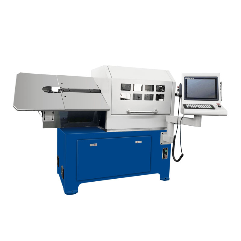 ZW-480 4AXES CNC SPRING WIRE BENDING MACHINEZW-480 4AXES CNC SPRING WIRE BENDING MACHINEView Product →
A four-axis machine of this type covers the majority of two-dimensional wire forms and simple three-dimensional parts: feed, rotation, and two bending directions. For shops producing hooks, clips, handles, frames and simple wire racks, that configuration is usually enough.
The right axis count is decided by the geometry of the part, not by the size of the budget. A useful way to plan it is to count how many independent motions the wire needs.
 TK-5120 5AXES CNC SPRING COILING MACHINETK-5120 5AXES CNC SPRING COILING MACHINEView Product →
A five-axis bender is the usual step up when a wire form has bends that twist out of plane, such as a retaining clip with an offset leg or a frame with a folded corner. Automotive and mobility suppliers often specify this class of machine because seat frames, linkage rods and cable ends combine several bend planes in one part; the requirements for that sector are summarised in the automotive and mobility wire forming applications overview.
Most bend defects traced back to a batch are set at the start of the run, not in the middle. Run through this list before the first good part is signed off.
 SLB-2800 WIRE FEEDING RACKAdditional InformationView Product →
Wire supply hardware is part of the bending process, not an accessory. A powered or free-running feeding rack with controlled tension removes a large share of the length variation that shows up as rejected parts three hours into a shift.
When a bend goes wrong, the symptom usually points to one of a small number of causes. The table below pairs the common defects with the correction that resolves them fastest.
| Defect | Likely cause | First correction |
|---|---|---|
| Crack or split on the outside of the bend | Radius below material minimum, or wire already work-hardened | Increase radius or move to a softer temper |
| Angle drifts across the run | Springback value too low, changing wire tension, tool wear | Retest springback, stabilise spool tension |
| Bend twists out of plane | Rotation axis misaligned, insufficient support near the bend | Recalibrate rotation, add a guide close to the tool |
| Flattened or oval section at the bend | Pin radius too small, clamping pressure too high | Match pin to 2R, reduce clamp force |
| Finished length short or long | Bend allowance ignored, feed slippage | Add bend allowance to the flat length, check roller grip |
A bend that looks right is not a bend that measures right. Three checks catch almost everything.
Sampling frequency should follow the process, not the calendar. A stable run with a settled springback value can be checked every fiftieth part; a run that has just been set up, or that uses a new wire lot, deserves a first-article check and a check at every tool change.
Clamp the wire in a vise with soft jaws, or hold it against a fixed pin, then pull the free end around a round form. The form diameter should be close to twice the inside radius you want, because the wire will spring back and open slightly. Mark the bend line from a datum first so the part stays dimensionally consistent.
It depends on the material and temper, and it is normally quoted as a multiple of the wire diameter. Annealed copper may accept half a diameter; music wire and oil-tempered spring steel typically need four to six diameters. Always confirm against the wire supplier's data sheet for the specific lot.
Measure it rather than guess. Bend a test piece, record the angle you achieved, and divide the target angle by that figure. Typical recovery runs from one to three degrees on annealed copper and up to fifteen degrees on hard spring steel, so the multiplier matters most on high-tensile wire.
Yes, within limits. Grades in the 0.5 mm to 2 mm range bend with good pliers and a jig if the radius is generous. Above that, the force and springback become difficult to control, and the risk of cracking at the outside of the bend rises sharply.
The outer surface has exceeded the strain the material can take. Three usual reasons: the inside radius is smaller than the material allows, the wire has already been work-hardened by an earlier operation, or the temper is too hard for the application. Calculating surface strain with d / (2R + d) quickly shows how far over the limit the design has gone.
Only when the required radius is tighter than the material allows in its current temper, or when the wire is thick enough that forming loads become impractical. Local heating lowers yield strength in the bend zone, but it also changes the properties of that zone, so parts that carry load should be evaluated afterwards rather than assumed to be fine.
Bending produces discrete angles and shapes on a wire that is fed through the machine. Coiling produces a continuous helix, where the wire is wrapped around a pitch and diameter that usually need a following stress-relief step. Many machines handle both, but the tooling, the control strategy and the tolerance focus are different.
Cut after the final bend, allow enough straight length for the cutting tool to grip without pulling the part, and set the springback correction on the last bend separately from the earlier ones. The final bend usually needs the most compensation because the part is no longer restrained by the rest of the wire form.
Bending wire well comes down to four decisions made in order: material and temper, inside radius measured against the strain formula, an overbend value taken from a real test piece, and a process that matches the quantity. Ten parts belong at a bench with a jig. Ten thousand parts with three bend planes belong on a servo-driven bender with a controlled wire feed and stored springback corrections.
Run the test bend first. Measure the angle, the radius and the finished length. Those three numbers tell you whether the job stays manual or moves onto a machine, and they give you the starting values for whichever route you choose.
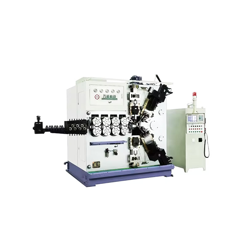
TK-6160 TK-6160 CNC SPRING ROLLING MACHINE...
See Details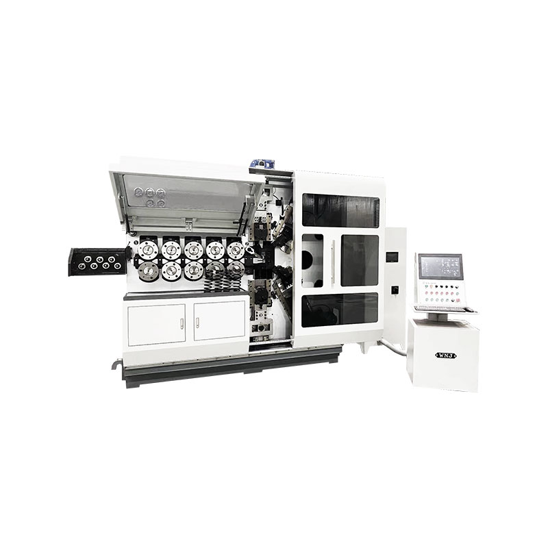
TK-6120 TK-6120 CNC SPRING ROLLING MACHINE...
See Details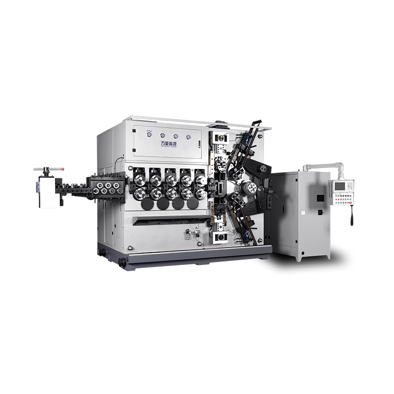
TK-5200 TK-5200 5AXES CNC SPRING COILING MACHINE...
See Details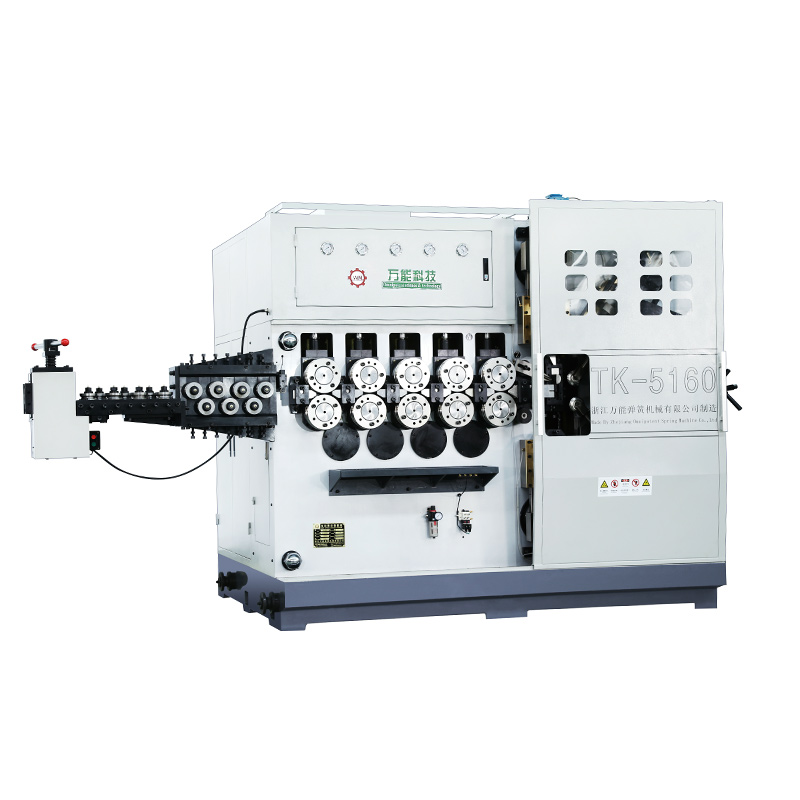
TK-5160 TK-5160 5AXES CNC SPRING COILING MACHINE...
See Details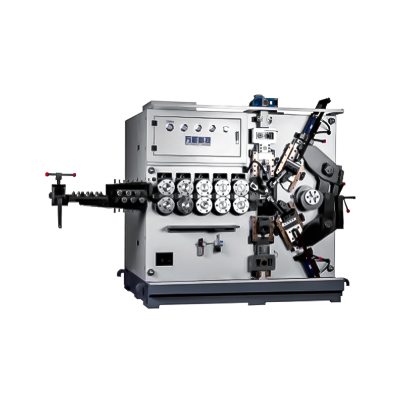
TK-5120 TK-5120 5AXES CNC SPRING COILING MACHINE...
See Details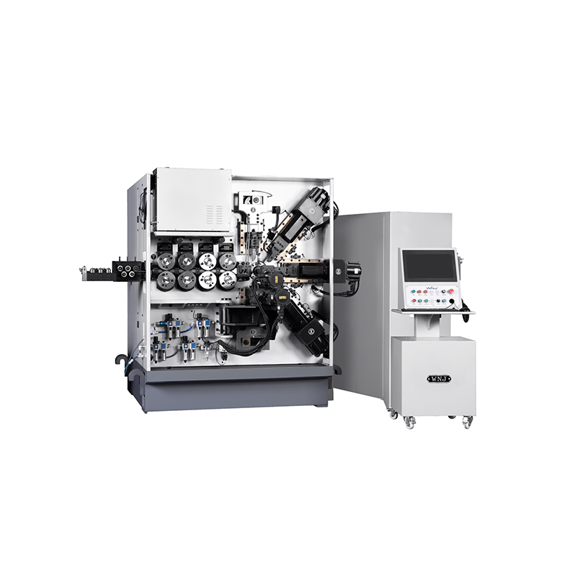
TK TK 10AXES CNC SPRING SCROLL MACHINE...
See Details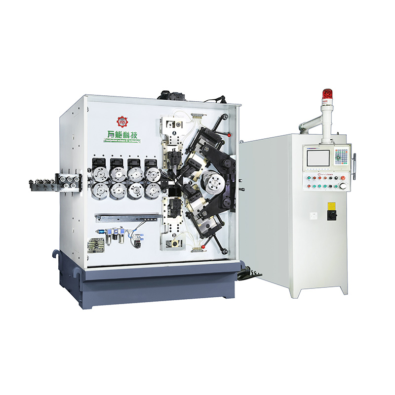
TK-580B、 TK-590 TK-580B、 TK-590 5AXES CNC SPRING COILING MACHINE...
See Details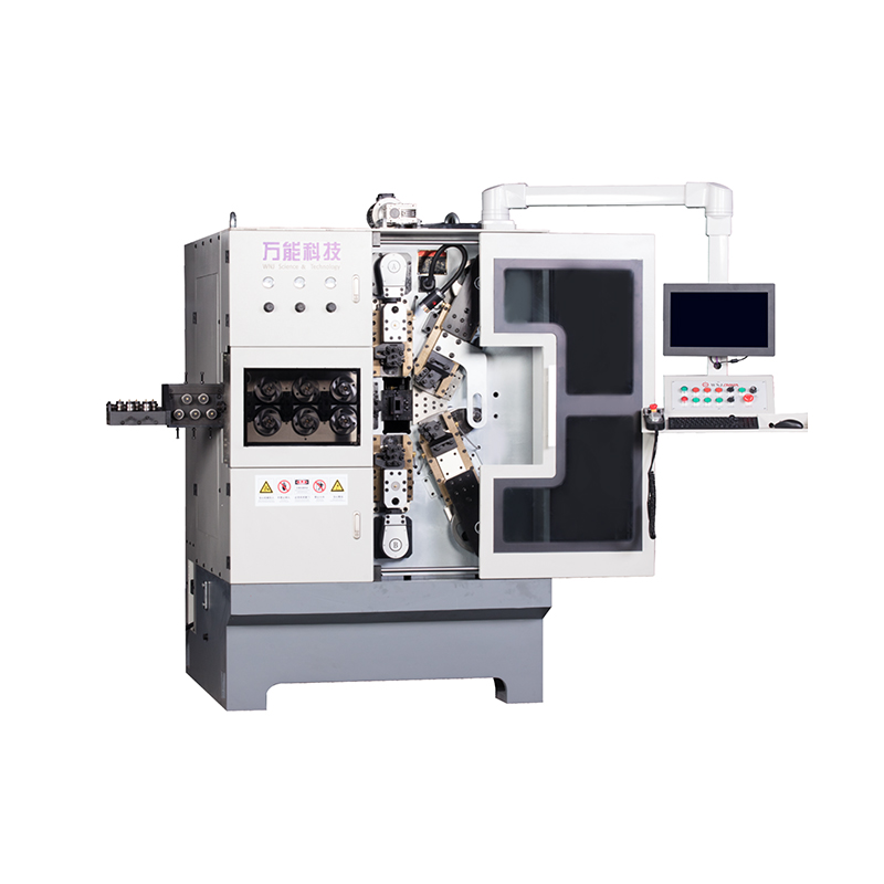
TK-760TK-760 6-7AXES CNC SPRING COILING MACHINE...
See DetailsMobile QR Code

 中文简体
 English
 русский
 Español