Language
Content
Five numbers decide the performance of every compression spring: wire diameter, mean coil diameter, number of active coils, free length, and the shear modulus of the wire material. Once these are set, spring rate, maximum stress, solid height, and usable deflection follow as fixed outputs. Get these five right and the rest of the design work is verification; get one wrong and the spring will sit badly in its bore, fatigue early, or never reach the target load.
The practical conclusion from more than 28 years of building spring manufacturing equipment is simple: start with the installed space and the load-deflection requirement, choose a spring index between 4 and 12, and let the spring rate formula do the heavy lifting. Then verify stress, check the length-to-diameter ratio, and always leave clearance above solid height. A compression spring that reaches solid height in service is a spring that will take a dramatic jump in stress.
The order matters. Do not start with free length or pitch. Start with d, D, Na, Lf, and G — everything else is derived.
A compression spring is an open-coil helical spring formed from round wire, with pitch between the coils so the spring can shorten when an axial compressive load is applied. When the load is removed, the spring returns to its original free length. The space between coils is not cosmetic: it defines the deflection capacity of the spring.
Compression springs are the most commonly produced spring type in the world. They appear in engine valves, suspension systems, door locks, electrical contacts, medical syringes, industrial safety valves, and aerospace actuators. In these applications, the spring performs one of three jobs: it resists a force, stores energy for release later, or returns a part to a defined position after displacement.
When a compression spring is compressed, the wire is twisted about its own axis. That twisting generates shear stress in the wire cross-section, and the measured result is a compressive force along the axis of the spring. In normal design, the spring works in the elastic range where deflection is proportional to load. The ratio of load to deflection is the spring rate, expressed in newtons per millimeter (N/mm) or pounds per inch (lb/in).
Designers specify compression springs when the force needs to remain predictable over a fixed travel, when assembly space is limited, or when the mechanism requires a simple and dependable restoring force. Compared with other spring types, a cylindrical compression spring is cheap to manufacture, easy to calculate, and straightforward to mass-produce on CNC spring coiling machines. The trade-off is that it needs lateral support if the free length is long relative to the mean diameter.
The table below lists the standard parameter set for a cylindrical compression spring. These symbols follow the conventions used in common spring design references, so they translate directly into the formulas in the next section.
| Parameter | Symbol | Unit | What it means for the design |
|---|---|---|---|
| Wire diameter | d | mm | Diameter of the round wire before coiling; the most powerful lever on spring rate. |
| Outer diameter | OD | mm | Largest diameter of the spring; controls the fit into a bore or housing. |
| Inner diameter | ID | mm | Must clear a guide rod; equals OD minus 2d. |
| Mean coil diameter | D | mm | Average of OD and ID; the diameter used in all spring rate and stress formulas. |
| Spring index | C | — | C = D/d. Recommended range is 4 to 12; low values cause high stress concentration. |
| Active coils | Na | — | Coils that actually deflect under load; end coils do not contribute. |
| Total coils | Nt | — | Active coils plus end coils; depends on end treatment. |
| Free length | Lf | mm | Unloaded length; defines travel and affects buckling risk. |
| Solid height | Ls | mm | Length when all coils touch; approximately Nt × d for closed ends. |
| Pitch | p | mm | Distance between corresponding points of adjacent coils in the free state. |
| Spring rate | k | N/mm | Load per unit deflection; the single most important output of the design. |
| Deflection | s | mm | Compression caused by load F; s = F/k. |
Spring index C is the ratio of mean diameter to wire diameter. A spring with C below 3 is very hard to coil without cracking the wire surface, because the inner side of the wire is compressed beyond practical limits. A spring with C above 12 is easy to coil but tangle-prone, sensitive to tolerance, and more likely to vibrate or surge. The design sweet spot is C between 4 and 12; for precision springs, aim for 6 to 10.
Only the active coils flex during compression. End coils that are pressed flat contact the next coil and no longer contribute to deflection. In a closed-and-ground end design with two end coils, the number of active coils equals total coils minus two. Using the wrong coil count in the formula is responsible for many failed spring prototypes.
Free length and solid height define the available travel. A spring can never be compressed to solid height in normal operation; doing so increases stress sharply and often leaves a permanent set. A common rule is to keep at least 10% to 15% of the maximum deflection as clearance above the solid height. Pitch is then set so the free length fits the assembly space while giving the needed travel.
End treatment is the first production decision in the design. It changes the number of active coils, the squareness of the spring, and the cost. There are four common end configurations for compression springs.
| End type | Active coils Na | End feature | Best suited for |
|---|---|---|---|
| Open (plain), not ground | Na = Nt | Wire end is cut, not pressed flat | Low-cost applications with short length or guided springs |
| Open (plain), ground | Na = Nt − 1 | Only the last coil is partially flattened | Better seating without closed ends |
| Closed (squared), not ground | Na = Nt − 2 | End coil is pressed closed but not flattened | General-purpose industrial springs |
| Closed (squared) and ground | Na = Nt − 2 | End coils closed and ground flat and square | Precision mechanisms, valve springs, load cells, high-cycle applications |
A closed-and-ground spring stands perpendicular to its seat, distributes load evenly across the ground face, and does not rotate as it compresses. This is why valve springs, medical-device springs, and instrument springs are almost always specified with closed and ground ends. The grinding operation also removes the wire surface layer at the ends, where cracks can start. The cost increase is modest, but the improvement in seating stability is significant.
If the spring is short and supported in a pocket, or if the load path is not critical, a plain end saves money. Industrial compression springs in lock mechanisms, electrical switches, and packaging machines commonly use plain or closed-not-ground ends. The design should still verify that the spring does not tip sideways at the start of compression.
The spring rate formula uses shear modulus G before any other material property. G is a material constant and does not change with heat treatment, cold working, or hardness. What heat treatment changes is the tensile strength, which sets the allowable stress. Therefore, the material choice fixes both the spring rate and the load capacity of the design.
For most applications the material decision comes down to a few questions: Does the spring see moisture or chemicals? What is the operating temperature? How many cycles will it survive? Is corrosion or electrical conductivity relevant? The table below lists the commonly used spring wire materials with their typical shear modulus and temperature limits. These values follow published material data used in spring design references such as the SAE spring design manuals and wire supplier datasheets.
| Material | Shear modulus G (N/mm²) | Max wire temperature (°C) | Typical use |
|---|---|---|---|
| Music wire (ASTM A228) | 79,300 | 120 | Small precision springs, sensors, valve parts |
| Oil-tempered wire (ASTM A229) | 79,300 | 150 | General industrial springs, automotive chassis parts |
| Hard-drawn steel (ASTM A227) | 79,300 | 120 | Low-cost springs with moderate cycle life |
| Chrome-vanadium (ASTM A231) | 79,300 | 220 | Fatigue and shock loads, engine springs |
| Chrome-silicon (ASTM A401) | 79,300 | 250 | High-stress valve springs, racing springs |
| Stainless 302/304 (ASTM A313) | 69,000–75,900 | 260 | Corrosion resistance, medical, food, marine |
| Phosphor bronze | 43,500 | 90 | Electrical contacts, corrosion environments |
| Inconel X-750 | 75,800 | 500 | High-temperature aerospace and power equipment |
Because the spring rate formula uses the fourth power of wire diameter, switching from carbon steel to stainless steel does not change the spring rate as much as people expect; the 10% to 15% drop in G can be compensated by a very small increase in d. The material comparison table above is a starting point, and the full selection logic including surface finish and wire feeding properties for production is covered in our guide to choosing spring material for spring machine production.
The spring rate of a cylindrical compression spring is:
k = G × d4 / (8 × D3 × Na)
where k is the spring rate in N/mm, G is the shear modulus in N/mm², d is the wire diameter in mm, D is the mean coil diameter in mm, and Na is the number of active coils. Keep all units consistent; mixing millimeters and meters is the most common error.
The direct shear stress formula for a helical spring under load F is 8FD/(πd³). This neglects the curvature of the wire, which concentrates stress on the inner side of the coil. The Wahl factor K_w corrects for that effect:
K_w = (4C − 1)/(4C − 4) + 0.615/C
where C is the spring index. The corrected shear stress is τ = K_w × 8FD/(πd³). At a spring index of 7, the Wahl factor is only about 1.21; at index 3, it climbs above 1.62. This is why you always check stress at low spring index.
Design a compression spring with music wire (G = 79,300 N/mm²), wire diameter d = 2.0 mm, mean coil diameter D = 14 mm, and Na = 8 active coils. Total coils with closed and ground ends: Nt = Na + 2 = 10.
Step 1 — Spring index: C = D/d = 14/2 = 7, inside the recommended 4 to 12 range.
Step 2 — Spring rate: k = 79,300 × 16 / (8 × 2,744 × 8) = 1,268,800 / 175,616 = 7.22 N/mm.
Step 3 — Deflection at a 120 N load: s = 120 / 7.22 = 16.6 mm. Free length is 45 mm, so the compressed length at load is 28.4 mm.
Step 4 — Solid height: Ls ≈ Nt × d = 10 × 2 = 20 mm. Clearance above solid is 28.4 − 20 = 8.4 mm, which is about 28% of the deflection travel — safely above the recommended 10% to 15% margin.
Step 5 — Stress check: K_w = 1.21; τ = 1.21 × 8 × 120 × 14 / (π × 8) = 647 N/mm². Typical allowable shear stress for music wire at this diameter is around 45% of the minimum tensile strength, roughly 900 N/mm², so the design operates with a comfortable but not excessive margin. These allowable-stress percentages come from standard spring design references, and the exact figure depends on the tensile grade of the wire delivered by the supplier.
A spring that looks perfect on paper can be difficult or expensive to produce. The rules below come from practical experience with coiling, grinding, and tempering equipment rather than from textbook theory alone.
Below 3, the wire surface on the inner radius strains too severely during coiling, and the mandrel sees excessive tool pressure. Above 12, the spring is fragile to handle, tolerances on diameter become harder to hold, and adjacent coils may touch under light side load. Most CNC spring machines produce their most stable quality between index 4 and 10.
A compression spring behaves like a slender column: above a certain free-length-to-mean-diameter ratio, it buckles sideways under load. For parallel-supported springs, the critical ratio is about 4. If Lf/D exceeds 4, the design needs a guide rod, an outer sleeve, or a conical spring shape. Buckling is a geometry problem, not a material problem; changing the wire grade will not fix it.
Typical manufacturing tolerances for compression springs scale with the spring index. A reasonable working assumption is an outer diameter tolerance of about ±1% for index up to 8 and ±1.5% to ±2% for index above 10. Free length tolerances of ±1% to ±2% are realistic; tighter free-length tolerance usually requires extra sorting or grinding. Spring rate tolerance follows from the wire diameter tolerance, so if you need a very precise rate, you must control d tightly upstream.
Multi-axis CNC coiling machines control pitch, diameter, feed length, and cut angle in a single pass. That means a design can include variable pitch, a reduced end coil, or a changing helix angle without changing tooling. A 5-axis CNC spring forming machine holds pitch accuracy in the range required for most precision helical springs, so the designer should specify pitch as a controlled dimension rather than a derived value. If the pitch is critical for surge behavior, note that in the drawing; a constant-pitch design is always easier to verify in production.
When the end coils are closed, the end surface is still irregular. Grinding flattens the end over the full wire width and makes the spring stand perpendicular. Grinding quality is judged by two outputs: the flat width of the ground face and the squareness of the end with respect to the spring axis. For precision assemblies, specifications commonly require that at least 75% of the wire end circumference is grounded flat. A CNC spring grinding machine controls the feed of the grinding wheels and the dwell time so the heat generated does not burn the wire surface. Over-grinding reduces the wire cross-section and weakens the end coils, while under-grinding leaves a rocking seat.
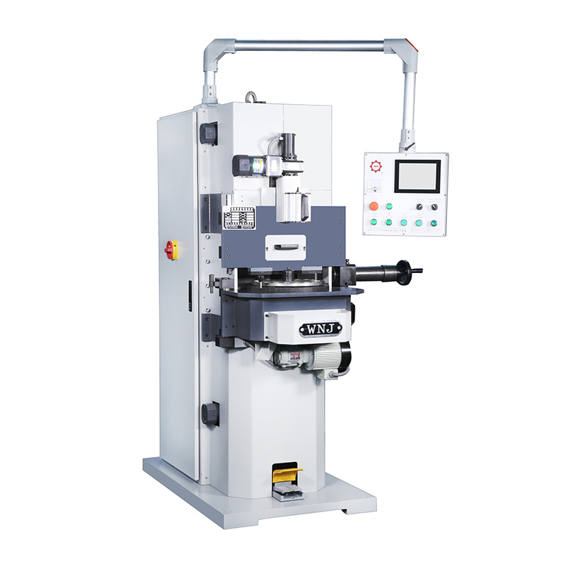 CNC Spring Grinding Machine Manufacturers, OEM/ODM Suppliers - WNJ MachineAs a China OEM/ODM CNC Spring Grinding Machine Manufacturers and Spring Grinding Machine Suppliers,Omnipotent Spring Machine Co.,ltd offe...View Product →
Coiling cold wire introduces significant residual stress, especially on the inner radius of each coil. Stress relief is done by heating the finished spring for a short time at a temperature that depends on the material: music wire is typically relieved around 180°C to 230°C, oil-tempered wire around 230°C to 260°C, and chrome-silicon alloys around 350°C to 430°C. The goal is to stabilize the dimensions and improve fatigue life without softening the wire. Tempering furnaces used in spring shops maintain uniform temperature across the load so every spring in the batch receives the same treatment; non-uniform tempering is a common cause of batch-to-batch variation in free length.
For springs that must survive millions of cycles, shot peening compresses the wire surface and pushes the origin of fatigue cracks below the stress field. Preset, also called compressive residual stress setting, involves compressing the spring to solid height once or several times to induce beneficial residual stress on the inner fiber. Both processes are standard for valve springs and suspension springs, but they add cost; use them only when fatigue life demands it.
Before committing to full production, run a small batch to verify three things: the measured spring rate, the free length after stress relief, and the solid height. If the measured rate is off, check the actual wire diameter first, because the fourth power magnifies even a 0.02 mm wire tolerance into a visible rate shift. Then check whether the active coil count matches the end treatment actually produced on the machine; a closed-and-ground spring made with one extra end coil will behave softer than calculated.
The machine type matters as much as the drawing. A pure cylindrical compression spring with constant pitch and ground ends is a standard job for a spring coiling machine followed by an end grinding machine. A spring with variable pitch, a conical shape, or a bent leg requires more axes. A 12-axis CNC spring camless machine handles complex geometry because every work axis moves independently and there is no cam to change between product families. The production route from wire to finished spring, including coiling, end grinding, and heat treatment, is described step by step in our article on how to manufacture springs.
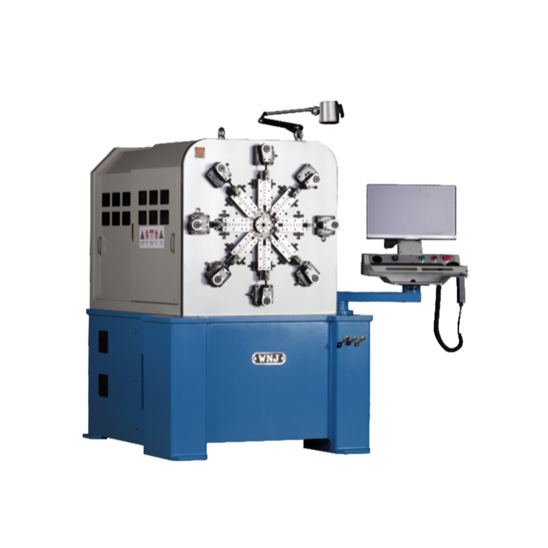 Custom CNC-1225 12AXES CNC SPRING CAMLESS MACHINE Factory, Comapny - WNJ MachineZhejiang Omnipotent Spring Machine Co.,ltd ( WNJ Machine ) is a China Wholesale CNC-1225 12AXES CNC SPRING CAMLESS MACHINE factory and co...View Product →
A compression spring that works in a door latch may fail in an automotive fuel injector, because the frequency of operation is different and the dynamic behavior of the spring changes. Compression springs used in automotive and mobility applications must be checked for surge frequency, fatigue life, and relaxation at operating temperature. The drawings produced by the designer are only the beginning; the production equipment must hold the geometry consistently over thousands of pieces.
Use k = G × d⁴ / (8 × D³ × Na). Measure d, D and Na in consistent units. The result is directly in N/mm when G is in N/mm² and all dimensions are in mm. The most frequent error is mixing wire gauge with physical wire diameter.
Aim for a spring index between 4 and 12, with 6 to 10 as the preferred zone for precision springs. Below 4 the wire is overstressed on the inner radius; above 12 the spring becomes difficult to handle, coil accurately, and measure consistently.
Specify closed and ground ends when the spring must stand perpendicular, sit in a recess with a flat seat, or carry a cyclic load. Valve springs, load cells, and medical instrument springs use closed and ground ends. Plain ends are acceptable for low-cost, low-cycle applications where the spring is guided by a rod or pocket.
Choose music wire for the highest strength and best fatigue life in a dry, interior, non-corrosive environment. Choose stainless 302 or 304 when the spring sees moisture, chemicals, or washdown, and accept that the lower shear modulus means a slightly larger wire diameter for the same spring rate. Stainless also retains useful strength to about 260°C, while music wire loses performance above 120°C.
Keep the free-length-to-mean-diameter ratio below about 4 for springs with parallel ends. If the ratio is higher, use a guide rod or an outer sleeve, or change to a conical or barrel-shaped spring. Buckling cannot be fixed by choosing a stronger material; it is a geometry problem.
Yes. A multi-axis CNC spring former moves the pitch tool and the wire feed independently, so the pitch can change along the spring axis in the same part. Variable pitch is used to control natural frequency and to reduce the solid height of long-travel springs. For consistent results, specify the pitch profile as a table of points on the drawing rather than a single nominal value.
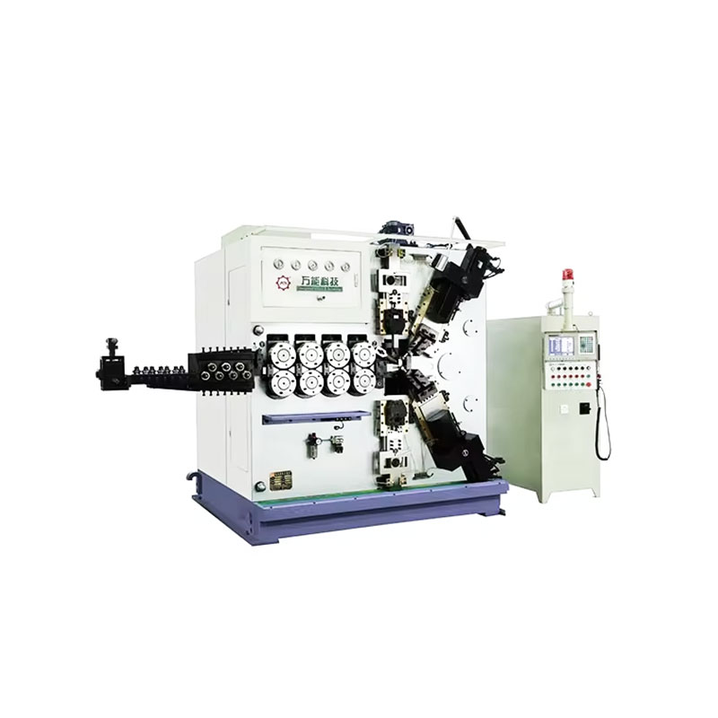
TK-6160 TK-6160 CNC SPRING ROLLING MACHINE...
See Details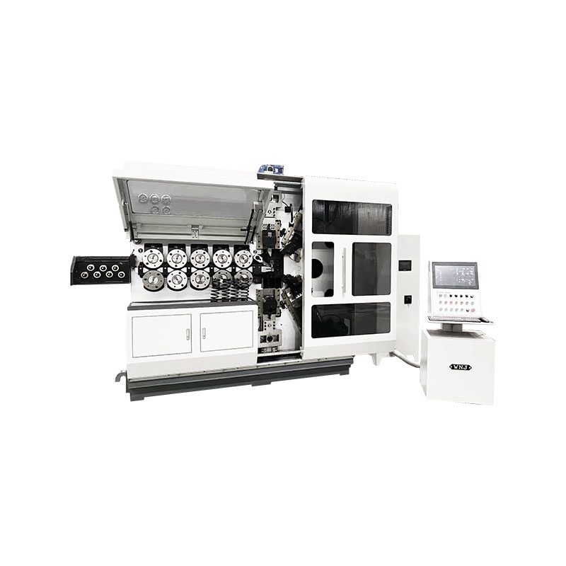
TK-6120 TK-6120 CNC SPRING ROLLING MACHINE...
See Details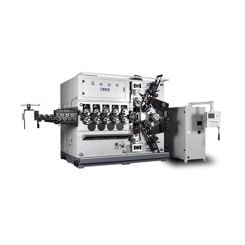
TK-5200 TK-5200 5AXES CNC SPRING COILING MACHINE...
See Details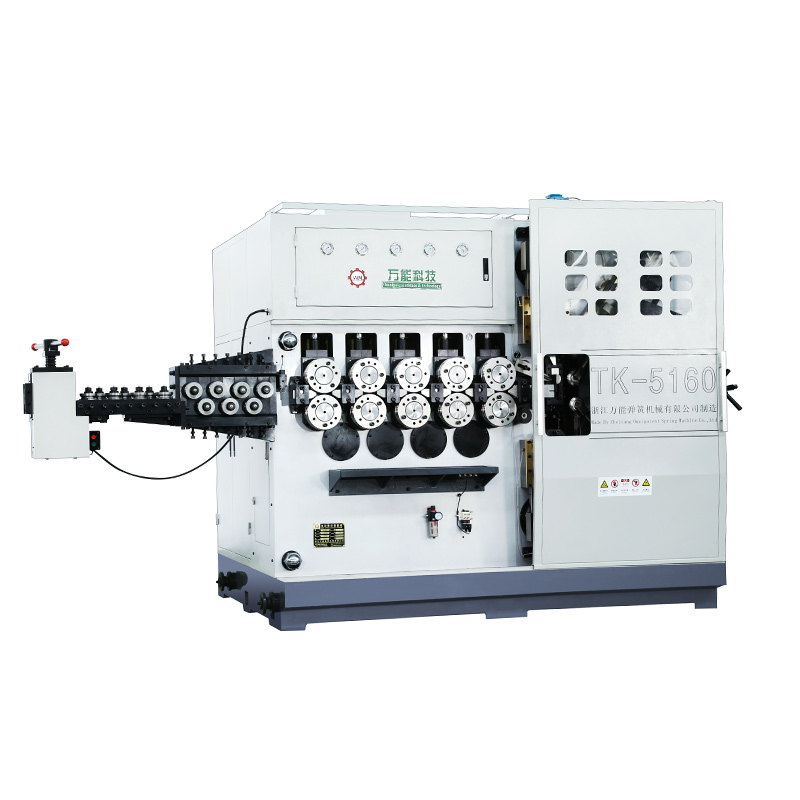
TK-5160 TK-5160 5AXES CNC SPRING COILING MACHINE...
See Details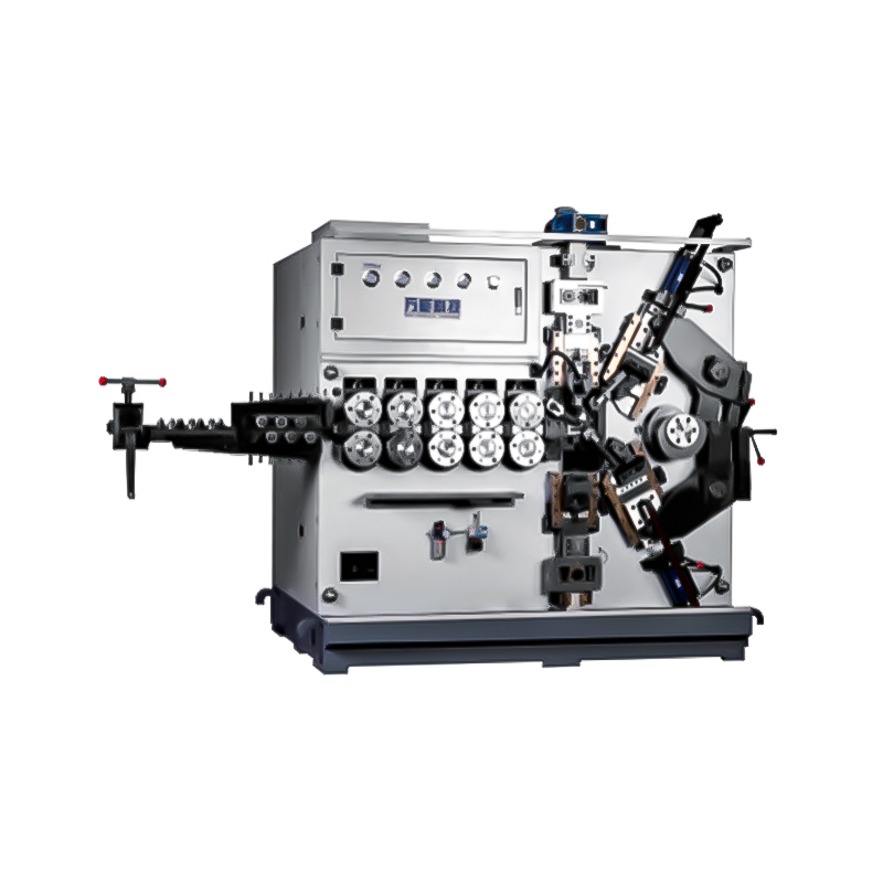
TK-5120 TK-5120 5AXES CNC SPRING COILING MACHINE...
See Details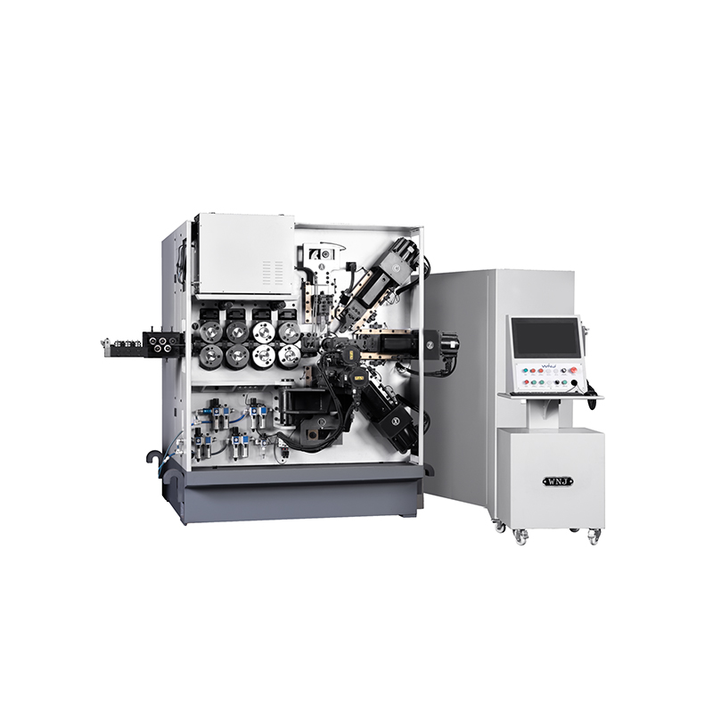
TK TK 10AXES CNC SPRING SCROLL MACHINE...
See Details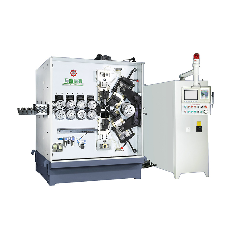
TK-580B、 TK-590 TK-580B、 TK-590 5AXES CNC SPRING COILING MACHINE...
See Details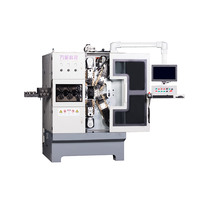
TK-760TK-760 6-7AXES CNC SPRING COILING MACHINE...
See DetailsMobile QR Code

 中文简体
中文简体 English
 русский
 Español