Content
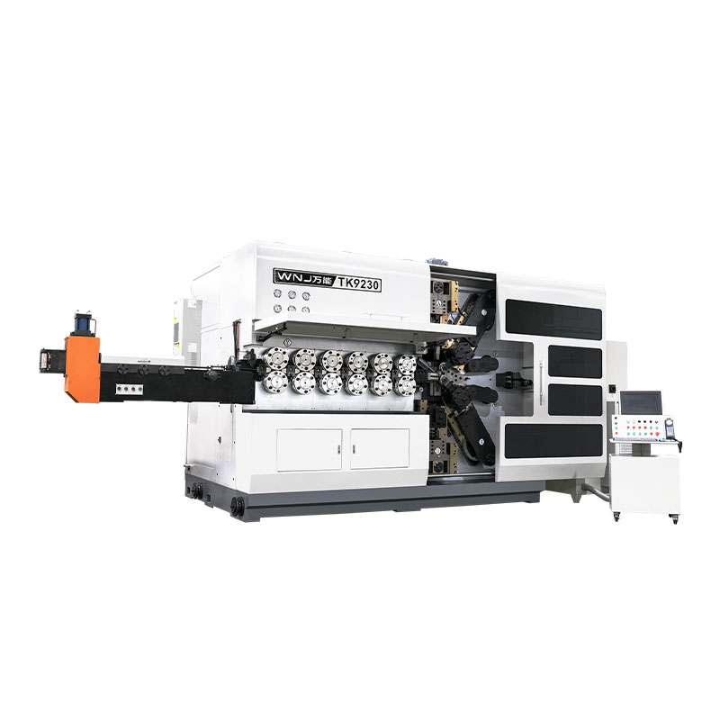
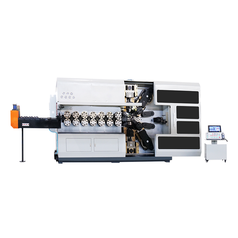
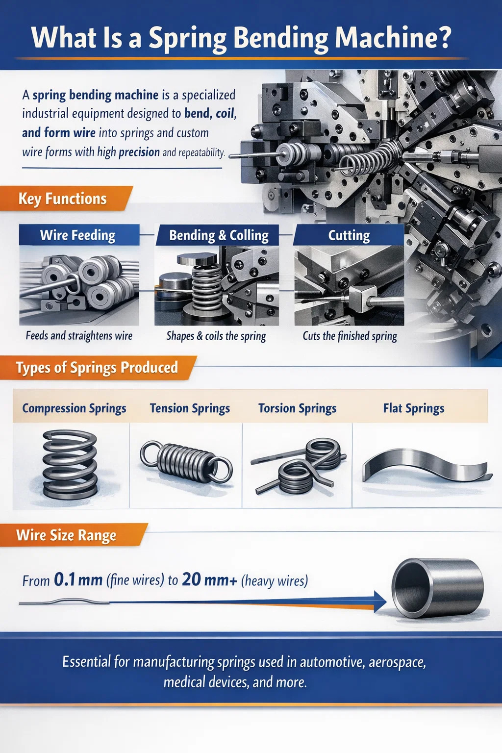
A spring bending machine is a specialized piece of industrial equipment designed to bend, coil, and form wire or strip material into springs and spring-like components. It controls the shape, pitch, diameter, and end configuration of each spring through a combination of feeding, bending, and cutting mechanisms. Unlike general-purpose wire forming machines, a spring bending machine is optimized specifically for producing compression springs, tension springs, torsion springs, flat springs, and custom-shaped wire forms with high repeatability and minimal manual intervention.
Spring bending machines handle wire diameters ranging from as fine as 0.1 mm (for precision electronic springs) to as thick as 20 mm or more (for heavy industrial suspension springs). In CNC-controlled models, a single machine can store hundreds of part programs and switch between spring types in minutes, making it a cornerstone of modern spring manufacturing.
The global spring manufacturing industry is substantial. Springs are used in virtually every mechanical product — from ballpoint pens and medical devices to automotive suspensions and aerospace actuators. The spring market was valued at over USD 24 billion in 2023, and spring bending machines are the primary production tools behind this output. Understanding what these machines are and how they work is essential for anyone involved in spring manufacturing, procurement, or engineering design.
The working principle of a spring bending machine centers on three coordinated actions: wire feeding, controlled bending, and cutting. These three functions are precisely timed and sequenced to produce a complete spring in a single continuous operation. Here is how each phase works:
Wire is drawn from a coil spool (or a straightened bar feeder for heavier wire) and passed through a series of straightening rollers. These rollers remove the natural curvature ("set") from the wire coil so that the wire enters the bending zone in a straight, consistent line. The straightening unit typically consists of two sets of rollers arranged at 90 degrees to each other — one set corrects the horizontal plane, the other corrects the vertical plane.
After straightening, a pair of servo-driven feed rollers grips the wire and pushes it forward at a controlled speed and length. The feed length determines where each bend will occur relative to the previous one, which directly controls the spring's pitch, body length, and end geometry. In CNC spring bending machines, the feed servo motor is programmed to deliver precise increments — sometimes accurate to ±0.01 mm per feed step.
As the wire is fed forward, it contacts bending tools (also called bending fingers, coiling pins, or pitch tools) that deflect it into the desired shape. In coil spring production, the wire is deflected around a coiling point (a hardened steel pin or mandrel) to produce the helical coil. The position of the coiling point relative to the wire path determines the coil diameter. The pitch tool — positioned axially along the wire — controls the spacing between adjacent coils.
The bending tools are mounted on slides or cams driven by servo motors (in CNC machines) or mechanical cams (in cam-type machines). In a CNC spring bending machine, each bending axis can be independently programmed to move to any position at any point during the wire feed cycle. This allows the machine to produce variable-pitch springs, barrel-shaped springs, conical springs, and complex 3D wire forms — all from a single setup.
For torsion springs and other non-coil forms, bending fingers apply a precise angular bend at specific points along the wire. The machine feeds a set length, bends at a programmed angle, feeds again, bends again — repeating until the full spring geometry is completed. Bend angles can be controlled to ±0.5 degrees or better on high-quality CNC machines.
Once the programmed spring geometry is complete, a cutting mechanism severs the wire to separate the finished spring from the incoming wire. The cutter is typically a hardened steel blade driven by a cam or servo axis. The cut must be clean and burr-free to avoid functional defects — especially for compression springs where the end coils must sit flat on a surface. Some machines include a dedicated end-forming station that grinds or flattens the cut ends after cutting, producing closed and ground ends required for precision compression springs.
A critical aspect of the spring bending machine's working principle is managing springback — the elastic recovery of the wire after bending. When a wire is bent, it deforms both plastically (permanently) and elastically. When the bending force is released, the elastic portion recovers, causing the wire to spring back partially toward its original shape. If not compensated, the finished spring will have a larger diameter and different pitch than programmed.
Springback depends on the wire material (stainless steel springs back more than mild steel), wire diameter, temper condition, and bend radius. CNC spring bending machines compensate for springback by overbending — setting the bending tool position beyond the nominal target by a calculated offset. In advanced machines, automatic springback measurement and compensation systems continuously adjust the tool positions based on measured spring dimensions from the previous few parts.
Spring bending machines are not a single category. Several distinct machine types exist, each suited to different spring types, production volumes, wire sizes, and complexity levels. Choosing the right machine type is as important as programming it correctly.
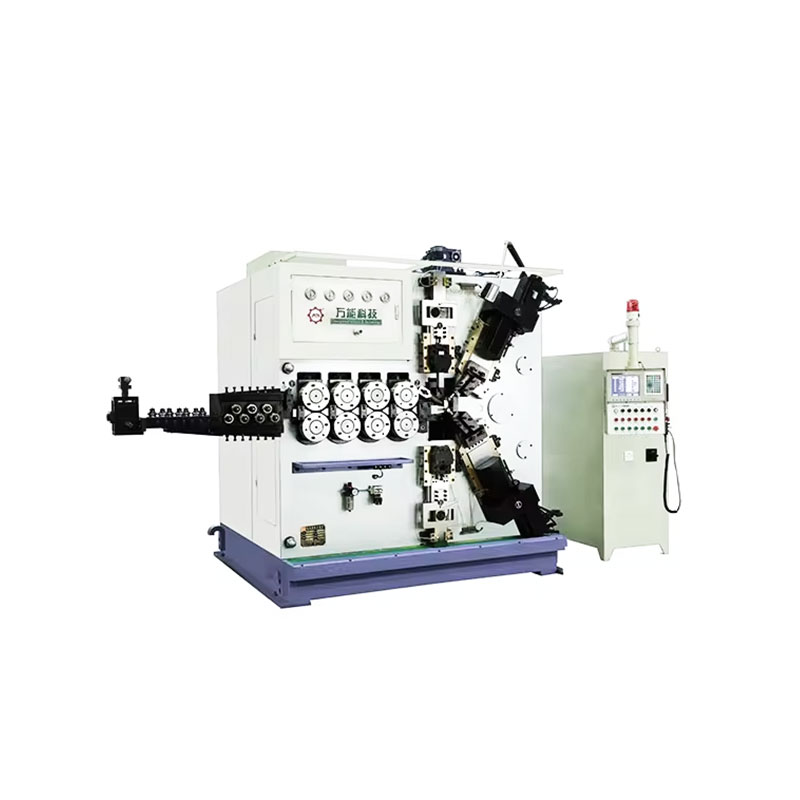
Cam-type coiling machines are the traditional workhorse of high-volume spring production. All axis movements are driven by mechanical cams mounted on a rotating camshaft. The cams are profiled to produce the desired spring geometry, and changing the spring design requires physically replacing or adjusting the cams. While setup is time-consuming, cam-type machines run at very high speeds — some models can produce up to 500 compression springs per minute — making them ideal for massive production runs of a single spring design. They are robust, reliable, and relatively low-cost to maintain.
CNC (Computer Numerical Control) spring coiling machines replace mechanical cams with servo motors on each axis. Each axis (coil diameter, pitch, feed, cut) is independently programmable through a touchscreen controller. Changing from one spring design to another is accomplished by loading a different program — no mechanical changeover is needed. CNC coiling machines typically have 4 to 8 CNC axes and can produce compression, extension, and variable-pitch springs. Production speeds range from 30 to 200 parts per minute depending on spring complexity and wire diameter.
Often called a CNC wire bending machine or CNC wire former, this type is distinct from coiling machines in that it can bend wire in three dimensions — not just coil it into a helix. With 8 to 16 or more CNC axes, these machines can produce complex 3D wire forms such as torsion springs with specific arm angles, wire clips, brackets, handles, and custom wire assemblies. The wire can be bent in any direction, rotated, and formed into virtually any shape. These machines are the most versatile type and are essential for custom spring and wire form manufacturing.
Flat spring bending machines (also called strip forming machines or flat wire spring machines) are designed for forming flat wire or metal strip into leaf springs, flat coil springs, clock springs, and stamped-and-formed flat spring components. They feed flat strip material through profiled rollers and bending dies that shape the strip in the horizontal and vertical planes. These machines are used extensively in the production of clock mainsprings, automotive leaf spring clips, and electrical contact springs.
Torsion spring machines are a specialized variant of CNC spring bending machines, optimized for producing torsion springs — springs that store energy by being twisted rather than compressed or stretched. They feature dedicated arm-bending tools that can bend the spring's leg/arm to precise angles (commonly 90°, 180°, or custom angles). The body coil is wound first, then the arms are bent. Torsion spring machines must precisely control leg length, leg angle, and coil direction (right-hand or left-hand winding).
| Machine Type | Spring Types Produced | Typical Wire Range | Production Speed | Changeover |
|---|---|---|---|---|
| Cam-Type Coiler | Compression, extension | 0.2–8 mm | Up to 500 ppm | Long (cam swap) |
| CNC Coiling Machine | Compression, extension, variable pitch | 0.1–20 mm | 30–200 ppm | Short (program load) |
| CNC Wire Former | Torsion, 3D wire forms, custom | 0.3–12 mm | 10–80 ppm | Short (program load) |
| Flat Spring Machine | Leaf springs, flat coil, contact springs | Flat strip 0.1–5 mm | 20–150 ppm | Medium |
| Torsion Spring Machine | Torsion springs | 0.2–10 mm | 20–120 ppm | Short (program load) |
Understanding what each major component does helps operators set up the machine correctly, troubleshoot defects, and maintain the equipment in good condition. Here are the core components found on most spring bending and coiling machines:
Spring bending machines can produce a wide range of spring types. Each type has distinct geometry, function, and manufacturing requirements. Here is a detailed overview of the most common spring types and how they are made:
Compression springs are open-coil helical springs that resist compressive (push) forces. They are the most commonly produced spring type globally, used in everything from ballpoint pens to automotive valve trains. They are produced by coiling wire into a helix with consistent pitch. Key parameters include free length, coil diameter (OD and ID), wire diameter, number of active coils, and end type (open, closed, open-ground, closed-ground). Closed and ground ends require a secondary grinding operation after coiling, where the end coils are ground flat on a disc or centerless grinder to provide a stable seating surface.
Extension springs are close-coiled helical springs that resist tensile (pull) forces. They are produced on coiling machines with a special hook-forming station that bends the wire end into a loop or hook for attachment. The body coils are wound with zero pitch (coils touching) to create initial tension — a pre-stress that must be overcome before the spring begins to elongate. Common hook types include machine hooks, German hooks, and crossover hooks, each formed by specific bending tool sequences programmed into the CNC controller.
Torsion springs store rotational energy by being twisted. They consist of a coiled body with two extending arms (legs). The spring exerts a torque proportional to the angle of twist. They are produced on CNC wire forming machines or dedicated torsion spring machines, where the body is coiled and then the arms are bent to the specified angle. Common applications include clothespins, mouse traps, garage door counterbalance systems, and precision instruments. The angle between the two arms — the "torsion angle" — must be held to ±1° or tighter for precision applications.
Flat springs are made from flat wire or metal strip rather than round wire. They include leaf springs (as used in vehicle suspensions), clock and power springs (flat coil springs wound from strip), cantilever springs, and electrical contact springs. Flat spring bending machines form the strip through profiled rollers and bending dies. Thickness tolerances for precision flat springs can be as tight as ±0.01 mm, which demands both precise strip material and a well-maintained machine.
Beyond classic spring shapes, CNC spring bending machines — especially multi-axis CNC wire formers — can produce virtually any shape from wire: clips, retaining rings, brackets, handles, medical guidewires, orthodontic wires, and complex 3D wire assemblies. These parts may not store elastic energy (so technically not springs) but are produced on spring bending machines using the same feed-bend-cut working principle.
The choice of wire material significantly affects the spring's performance, the machine setup, and the springback compensation required. Different materials have different elastic moduli, tensile strengths, and springback characteristics. Here are the most common wire materials processed by spring bending machines:
Setting up and operating a spring bending machine correctly requires a systematic approach. Here is the typical sequence for setting up a CNC spring coiling machine to produce a new compression spring:
Spring engineers and machine operators need to understand the relationship between machine settings and spring parameters. Here is how the most critical spring dimensions are controlled on a CNC spring bending machine:
| Spring Parameter | Machine Control | Typical Tolerance Achievable | Key Factors Affecting Accuracy |
|---|---|---|---|
| Coil Outer Diameter (OD) | Coiling point position | ±0.05–0.2 mm | Springback, wire diameter variation |
| Free Length | Wire feed length per spring | ±0.1–0.5 mm | Feed roller slip, wire elongation |
| Pitch | Pitch tool position | ±0.05–0.2 mm | Springback, wire stiffness |
| Number of Coils | Wire feed length and cut timing | ±0.1–0.5 coils | Cut timing, pitch consistency |
| Spring Rate | Indirectly (OD, pitch, coil count) | ±5–10% | Wire modulus variation, all geometry |
| Arm Angle (Torsion) | Bending tool angle | ±0.5–2° | Angular springback, wire hardness |
The shift from manual and cam-type spring machines to fully CNC spring bending machines has been one of the most significant changes in spring manufacturing over the past 30 years. The advantages of CNC are compelling and well-documented in production environments:
Even well-set-up spring bending machines produce defective parts when process conditions drift. Recognizing common defects and their root causes is essential for maintaining quality:
The spring bending machine industry has a relatively small number of well-established manufacturers, most of them based in Europe and Asia. Here are some of the most recognized names in the industry:
Machine pricing varies enormously by capability. A basic CNC spring coiling machine for standard wire sizes can start at USD 30,000–80,000, while a high-end multi-axis CNC wire forming machine from a premium European manufacturer can exceed USD 300,000–500,000 when fully tooled and equipped with automatic inspection systems.
Springs are among the most universally used mechanical components. Spring bending machines are directly responsible for producing the springs used across an extraordinary range of industries and products:
Spring bending machines involve high-speed rotating and reciprocating parts, high-tension wire, and sharp cutting tools. Proper safety practices protect operators and maintain machine reliability:
TK-6160 TK-6160 CNC SPRING ROLLING MACHINE...
詳細を見る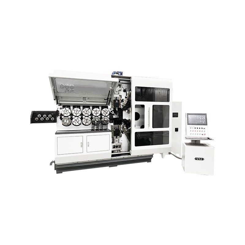
TK-6120 TK-6120 CNC SPRING ROLLING MACHINE...
詳細を見る
TK-5200 TK-5200 5AXES CNC SPRING COILING MACHINE...
詳細を見る
TK-5160 TK-5160 5AXES CNC SPRING COILING MACHINE...
詳細を見る
TK-5120 TK-5120 5AXES CNC SPRING COILING MACHINE...
詳細を見る
TK TK 10AXES CNC SPRING SCROLL MACHINE...
詳細を見る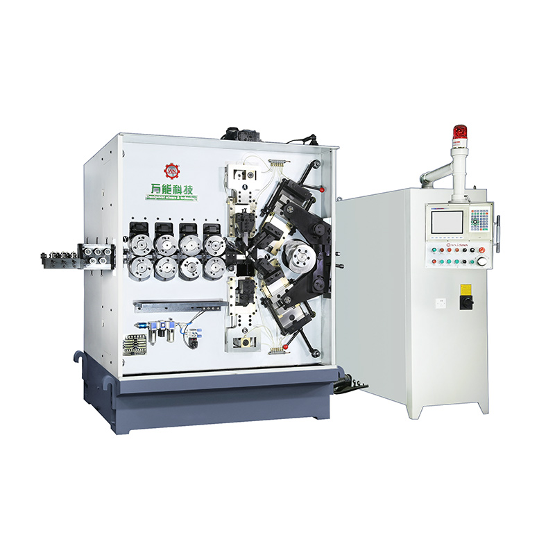
TK-580B、 TK-590 TK-580B、 TK-590 5AXES CNC SPRING COILING MACHINE...
詳細を見る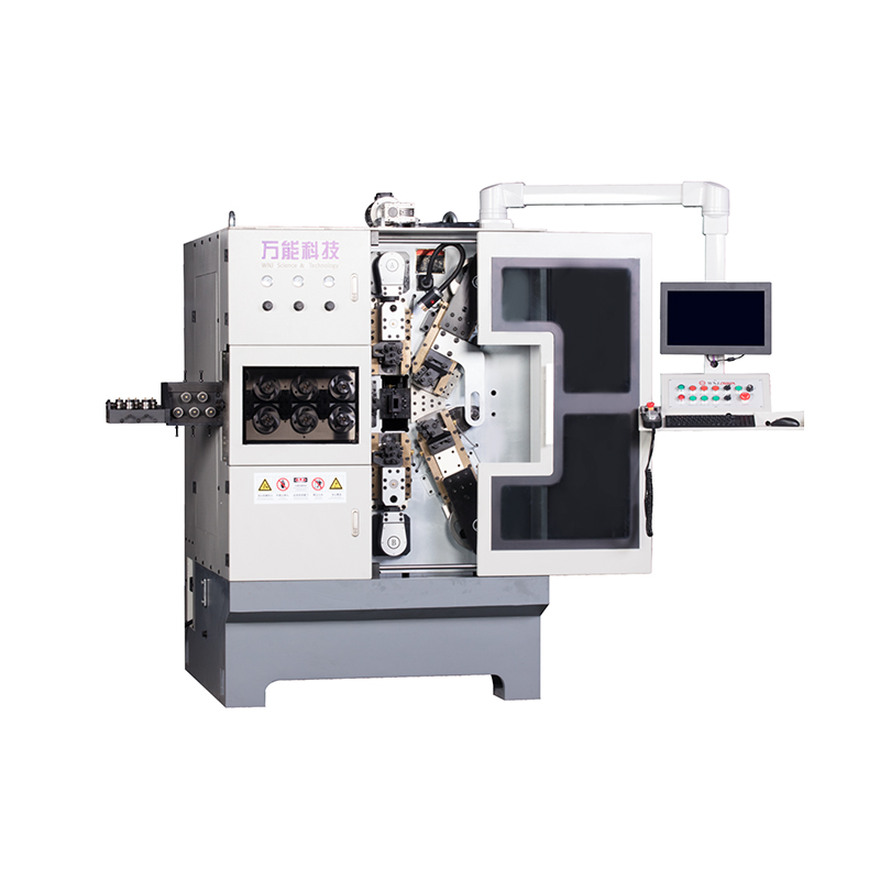
TK-760TK-760 6-7AXES CNC SPRING COILING MACHINE...
詳細を見るMobile QR Code

 Language
  中文简体
中文简体 English
 русский
 Español