Language
Content
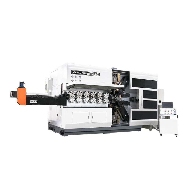
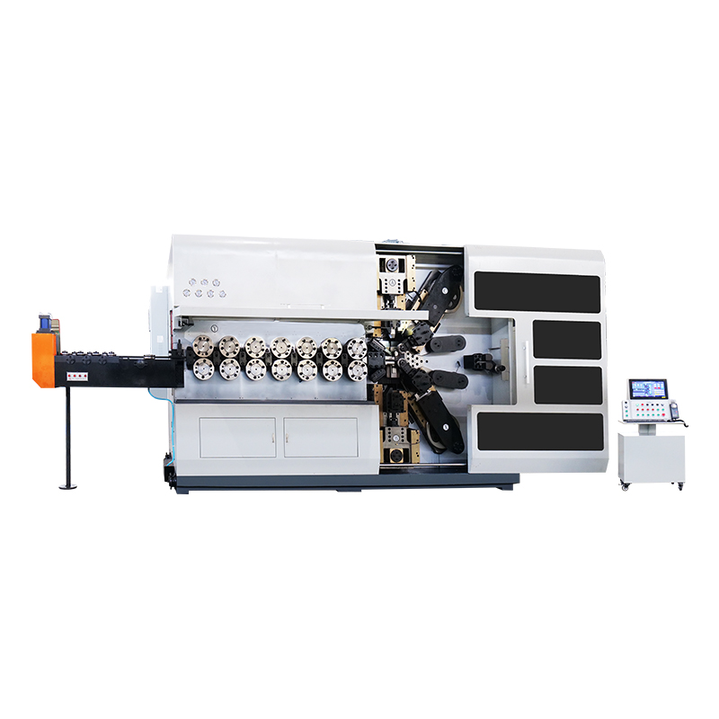
The process of bending is a metal forming operation that applies controlled force to a workpiece until it deforms plastically around a die, mandrel, or roller, changing its shape without cutting away material. The short answer is this: bending works because metal has an elastic zone and a plastic zone, and every successful bend depends on pushing the material past the elastic limit just far enough that it holds the new shape once the load is removed, known as springback. A spring bending machine is the equipment purpose built to control that exact transition for coil springs, torsion springs, and wire forms, using rotating tools, pins, and CNC-driven axes to repeat the same bend thousands of times with almost no variation. The rest of this article breaks down how that process actually happens on the shop floor, what separates a good spring bending machine from a mediocre one, and how to keep bend angles consistent across a full production run.
Bending is not one single action. It is a sequence of mechanical events that happen in fractions of a second, and understanding each stage explains why some bends crack, some spring back too far, and some hold a perfect angle every time.
When force is first applied to a wire or sheet, the material stretches or compresses within its elastic range. If the load were removed at this point, the metal would return to its original shape completely. No permanent bend has occurred yet.
As force increases past the yield point, the outer fiber of the bend stretches permanently while the inner fiber compresses. This is the actual moment the process of bending creates a lasting shape, and the neutral axis, the line inside the material that neither stretches nor compresses, shifts slightly toward the inner radius as the bend tightens.
Once tooling releases the material, stored elastic energy causes the bend to relax slightly toward its original shape. A spring bending machine compensates for this by overbending a calculated amount, usually between 2 and 8 degrees depending on wire diameter, tensile strength, and heat treatment condition.
| Material | Typical Tensile Strength | Average Springback |
|---|---|---|
| High carbon spring steel | 1900 to 2200 MPa | 5 to 8 degrees |
| Stainless steel 302 or 304 | 1300 to 1600 MPa | 3 to 6 degrees |
| Music wire ASTM A228 | 2200 to 2500 MPa | 6 to 9 degrees |
| Phosphor bronze | 700 to 900 MPa | 2 to 4 degrees |
Modern CNC spring bending machines break a single bend cycle into a repeatable sequence. Each step is programmed as an axis movement, and the controller synchronizes wire feed, rotation, and tool engagement so the whole cycle completes in well under a second for simple forms.
Not every bending operation uses the same equipment or the same physics. Understanding where a spring bending machine fits relative to sheet metal bending helps buyers avoid ordering the wrong tool for the job.
Press brake bending forms flat sheet or plate between a punch and die, producing a single straight line bend per stroke. It suits panels, brackets, and enclosures rather than wire or round bar forms.
Roll bending passes material through three or four rollers to create large radius curves, commonly used for cylinders, tanks, and structural curved sections rather than tight precision geometry.
Rotary draw bending clamps tube or pipe against a fixed radius die and rotates it around that die, producing tight radius bends with minimal wall thinning, widely used in automotive exhaust and roll cage fabrication.
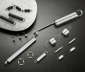
A spring bending machine, sometimes called a CNC wire forming machine, handles thinner round wire stock at high cycle rates, producing torsion springs, compression spring hooks, extension spring loops, and custom wire forms with multiple bends per part rather than one long straight bend.
Coil winding wraps wire helically around a mandrel to form the body of a compression or extension spring, and it is often paired with bending on the same machine when the finished part needs both a coiled body and formed end hooks or legs. On a combination coiling and bending machine, the same wire feed and straightening system serves both functions, with a separate pitch tool controlling the helix angle during the winding stage before the bending head takes over to form the ends.
Four slide machines add horizontal forming tools that approach the wire from multiple directions, useful for parts that combine bending, coiling, and flattening in a single cycle. These machines sit at the upper end of wire forming complexity and typically justify their cost only for parts with intricate geometry that cannot be produced on a standard two axis or four axis spring bending machine.
Specification sheets from different manufacturers are not always presented the same way, so it helps to know exactly which numbers actually predict real world performance rather than simply comparing headline claims.
| Specification | Typical Range | Why It Matters |
|---|---|---|
| Wire diameter range | 0.1 to 8 millimeters | Sets which product families the machine can run without retooling the whole feed path |
| Number of controlled axes | 4 to 12 | Determines how many bend directions and tool stations can act in one pass |
| Maximum feed speed | 200 to 600 meters per minute | Directly caps theoretical parts per minute for simple geometry |
| Bend head rotation speed | 300 to 1000 degrees per second | Affects cycle time on parts with many small bends rather than one large bend |
| Memory or program storage | 50 to 500 stored programs | Relevant for shops running many different part numbers with frequent changeovers |
| Repeat positioning accuracy | 0.01 to 0.05 millimeters | Predicts how tight a dimensional tolerance the machine can hold over a long run |
Buyers evaluating a spring bending machine for a specific part family should request a sample run on their own wire lot whenever possible. Published specifications describe the machine's theoretical ceiling, but actual performance always depends on the interaction between the machine, the specific alloy, temper, and coil set of the wire being run, and the tooling selected for that job.
The accuracy of any spring bending machine comes down to five subsystems working in coordination rather than any single part. A weak link in any one of these areas shows up immediately as inconsistent bend angles or part rejects.
The same bend program produces different results on different wire materials, because the process of bending is governed as much by metallurgy as by machine geometry. Choosing the right material for the application, and understanding how that material behaves under the bend head, prevents a large share of production problems before they start.
High carbon spring steel offers the highest strength to cost ratio among common spring wire materials and is the default choice for general purpose torsion, compression, and extension springs. It requires higher bending force and a larger springback allowance than softer alloys, and it typically benefits from a stress relief heat treatment after forming to stabilize the finished shape.
Stainless steel wire, most commonly grade 302 or 304, trades some strength for corrosion resistance and is chosen for parts exposed to moisture, chemicals, or food contact environments. It work hardens faster than carbon steel during forming, so bend sequences involving multiple tight radius bends in the same location need to be programmed carefully to avoid cracking.
Music wire, also called piano wire, is a high carbon steel drawn to a very tight diameter tolerance and a very high tensile strength, making it the material of choice for small precision springs where consistent force output matters more than raw size. Its high strength means a spring bending machine must apply more overbend compensation to hit target angles.
Phosphor bronze and beryllium copper are chosen when electrical conductivity is required alongside spring properties, common in electronic contact springs and connector clips. These materials are softer than steel alloys, bend at lower force, and show less springback, which generally makes them easier to hold tight tolerance on but more prone to permanent set under sustained load if overstressed.
Programming has shifted from manual teach in methods toward CAD driven workflows, and the software layer now plays as large a role in production efficiency as the mechanical hardware itself.
The oldest programming method involves an operator stepping through each axis movement at the machine control panel, saving each position as it is confirmed correct. This method works for simple parts but becomes slow and error prone as bend count increases.
Modern spring bending machine software accepts a 2D or 3D drawing of the finished part and automatically calculates axis movements, bend sequence, and estimated cycle time before the program ever touches the physical machine. This lets engineering teams validate a design and estimate tooling needs without consuming shop floor time.
Advanced programming packages simulate the full bend sequence in software, flagging any point where the wire, tooling, or bend head geometry would collide before the program runs on the actual machine. This step has meaningfully reduced tooling damage and scrapped setup time compared to purely manual verification.
Shops running high product mix benefit from a searchable program library, since a previously validated bend program can be recalled in seconds rather than reprogrammed from scratch, cutting changeover time from hours down to minutes on repeat orders.
To make the process concrete, here is how a typical torsion spring leg bend runs from raw wire to finished part on a CNC spring bending machine.
An operator or programmer inputs leg length, bend angle, coil body length, and wire diameter into the CNC interface, either through manual entry or CAD import.
The correct bend pin diameter is selected to match the spring's inside diameter, since the pin governs the radius of the coiled body and any formed legs.
The machine cycles at reduced speed without cutting off parts so the operator can confirm the toolpath clears all fixtures before full production speed begins.
The first completed part is measured against the drawing tolerance, typically plus or minus 2 degrees on leg angle and plus or minus 0.1 millimeters on leg length, before the run continues.
Once approved, the spring bending machine runs continuously, often producing 60 to 200 parts per minute depending on wire diameter and geometry complexity.
| Machine Type | Repeatability | Best Suited Volume |
|---|---|---|
| Manual bending jig | Operator dependent | Prototype or under 50 pieces |
| Semi automatic bender | Moderate, tooling controlled | Small batch, 50 to 5000 pieces |
| CNC spring bending machine | High, program controlled | Production runs above 5000 pieces |
Buyers should match machine type to actual order volume rather than choosing the most advanced option automatically. A CNC spring bending machine only pays for itself once changeover time savings and rejection rate reduction offset the higher upfront cost, which typically happens somewhere between 3000 and 8000 pieces per part number depending on part complexity.
Cracking happens when the bend radius is too tight relative to wire diameter or when the material has become work hardened from prior forming. Increasing bend radius or annealing the stock before bending resolves most cracking issues.
Angle drift across a production run usually traces back to bend pin wear, feed roller slippage, or temperature changes in the shop affecting material stiffness slightly over the shift.
Surface scarring appears when guide channels or bend pins have rough surface finish or debris buildup, which is why routine tooling cleaning is part of standard spring bending machine maintenance.
Complex multi bend parts can twist if wire guide support is insufficient during a bend, so proper fixture design and adequate guide length close to the bend point prevent this defect.
The first several parts after a cold start sometimes show slightly different angles than the rest of the run, because tooling and machine frame temperature have not yet stabilized. Running a short warm up cycle before first article inspection reduces this effect substantially.
Wire delivered from different production lots, even of the same nominal specification, can carry slightly different coil set and residual stress from the drawing process. Shops that requalify bend programs whenever a new wire lot arrives catch this variation before it reaches a customer.
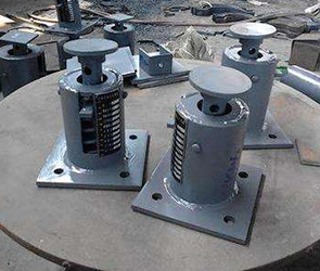
The spring bending machine category has moved noticeably toward smarter, more connected equipment over recent product generations, and several trends are now common on new machine purchases rather than optional upgrades.
Formed wire and spring components produced through precision bending processes show up across a wide range of industries, often in parts that never get noticed until they fail.
A spring bending machine that produced parts within tolerance on day one will not stay that way without a maintenance routine. Shops that track tooling wear against a schedule rather than waiting for rejects to appear consistently report fewer scrapped parts.
| Component | Inspection Interval | Typical Wear Sign |
|---|---|---|
| Bend pins and quills | Every 50000 cycles | Radius flattening or scoring |
| Straightening rollers | Every 100000 cycles | Surface grooving or pitting |
| Feed rollers | Every 75000 cycles | Slippage or reduced grip texture |
| Cutoff blade | Every 30000 cycles | Burr formation on cut end |
The line running through the cross section of a bent wire or sheet where material is neither stretched nor compressed during the bend.
Residual curvature left in wire from being wound on a spool, which must be removed by straightening rollers before an accurate bend can be made.
The extra angle a spring bending machine adds beyond the target angle to account for springback once the tooling releases the wire.
A fixed pin or rod around which wire is coiled or bent to establish the inside diameter of the finished feature.
A rotating tube or sleeve on the bend head that carries the wire guide and bend pin assembly through its programmed rotation.
The progressive increase in stiffness and reduction in ductility a metal undergoes as it is repeatedly deformed, which can lead to cracking if a wire is bent too many times in the same location.
A secondary operation, sometimes performed on the same spring bending machine, that compresses or deflects a finished spring slightly beyond its working range to stabilize its final free length or angle.
Bending is a specific type of forming that changes shape along a defined line or axis using a punch, roller, or pin, while forming is the broader category that also includes drawing, stamping, and coining operations.
Springback scales with a material's yield strength divided by its elastic modulus, so higher strength materials like music wire spring back more than softer alloys like phosphor bronze at the same bend angle.
A common starting guideline is a minimum bend radius of one to two times the wire diameter for most spring steels, though harder tempers may require a larger radius to avoid cracking.
Many CNC spring bending machines are configured specifically for round wire, but flat wire and strip forming machines exist as a related but distinct category with different guide and roller tooling.
Well maintained CNC spring bending machines commonly hold angle tolerances of plus or minus 1 to 2 degrees and length tolerances of plus or minus 0.1 millimeters on standard wire diameters.
Yes, thinner wire generally allows faster feed rates and bend speeds, while thicker or higher strength wire requires slower, more controlled bending to avoid tooling stress and premature wear.
Simple parts may need only one or two bends, while complex wire forms produced on multi axis machines can include fifteen or more individual bend, coil, and cutoff operations within a single continuous cycle.
Not always, but many high carbon and music wire parts benefit from a low temperature stress relief bake after forming, which reduces residual stress and improves dimensional stability without significantly changing hardness.
Accuracy loss almost always traces back to tooling wear, feed roller slippage, or accumulated backlash in the drive mechanism, all of which are addressed through the scheduled maintenance intervals described earlier in this article.
Yes, most CNC spring bending machines can switch between compatible materials by adjusting feed force, straightening roller pressure, and overbend compensation values in the program, though very different wire diameters may require a physical tooling change.
Simple parts with two or three bends can often be programmed and validated within a single shift, while complex multi bend geometry with tight tolerances may take several days of programming and first article iteration before full production release.
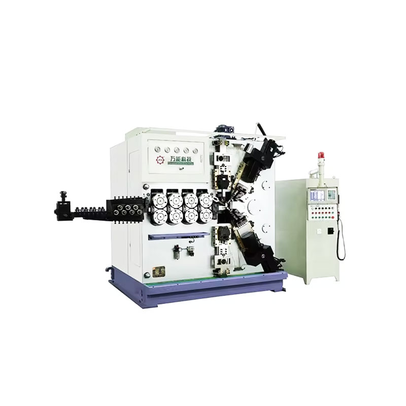
TK-6160 TK-6160 CNC SPRING ROLLING MACHINE...
See Details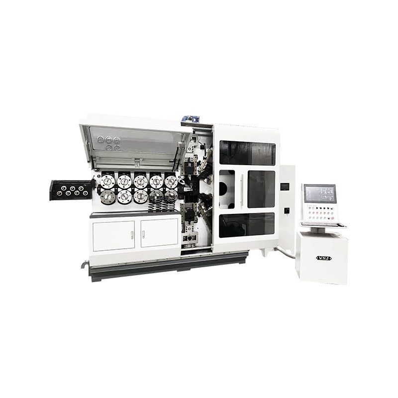
TK-6120 TK-6120 CNC SPRING ROLLING MACHINE...
See Details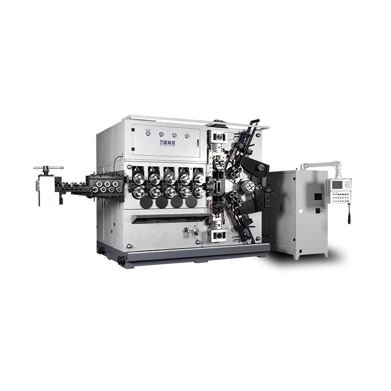
TK-5200 TK-5200 5AXES CNC SPRING COILING MACHINE...
See Details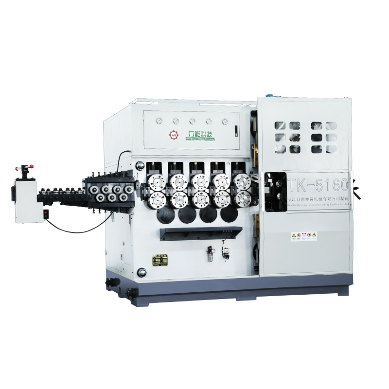
TK-5160 TK-5160 5AXES CNC SPRING COILING MACHINE...
See Details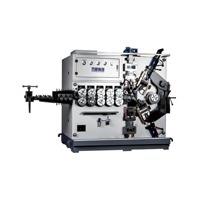
TK-5120 TK-5120 5AXES CNC SPRING COILING MACHINE...
See Details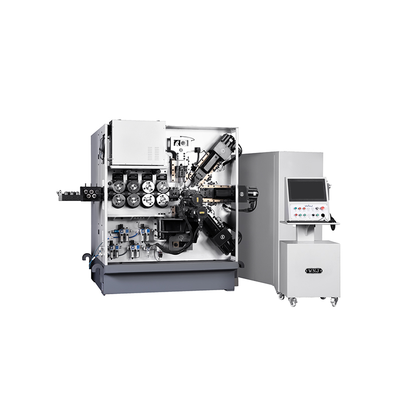
TK TK 10AXES CNC SPRING SCROLL MACHINE...
See Details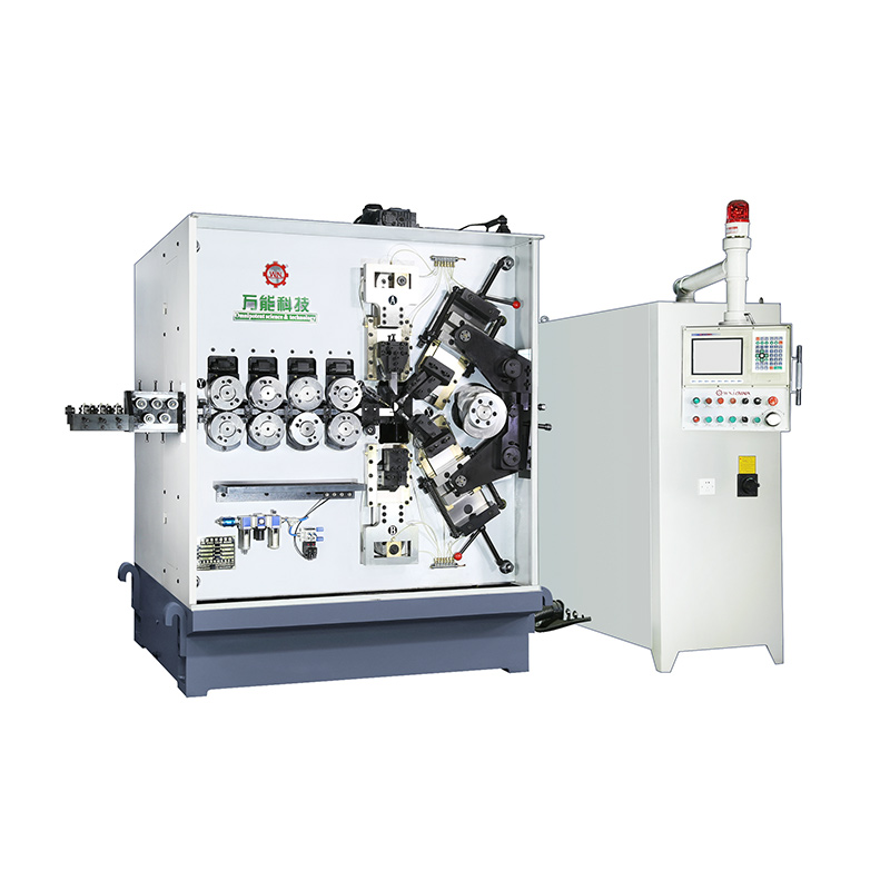
TK-580B、 TK-590 TK-580B、 TK-590 5AXES CNC SPRING COILING MACHINE...
See Details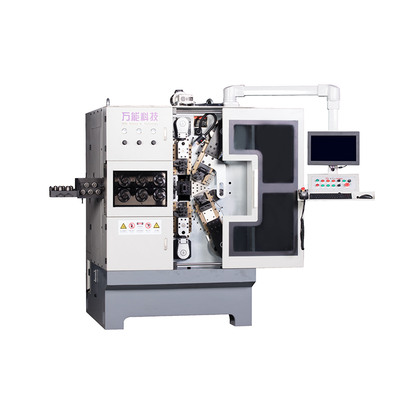
TK-760TK-760 6-7AXES CNC SPRING COILING MACHINE...
See DetailsMobile QR Code

 中文简体
中文简体 English
 русский
 Español