Language
Content
A compression spring design only works when the load, deflection, and fatigue requirements are balanced with the capabilities of the machinery that forms it. Start with the spring rate, then check stress and solid height, and finally confirm the tolerances with the production team. Getting this sequence right saves weeks of trial and error.
This guide walks through the core design parameters, a step-by-step calculation example, typical manufacturing tolerances, and the equipment choices that determine whether your compression spring can be built consistently.
The spring rate (k) is the most important design value. It defines the load required to compress the spring by one millimeter. The formula for a helical compression spring is k = G d^4 / (8 D^3 Na), where G is the shear modulus, d is wire diameter, D is mean coil diameter, and Na is the number of active coils. Increasing wire diameter has the strongest effect on rate because it is raised to the fourth power; increasing mean diameter or active coils makes the spring softer.
Other parameters include free length, solid height, pitch, total coils, index ratio, and stress. The spring index C = D/d should normally be between 4 and 12. A lower index puts more stress on the inside of the coil; a higher index makes the spring likely to buckle and sensitive to side loads.
| Parameter | Symbol | Typical range | Effect on performance |
|---|---|---|---|
| Wire diameter | d | 0.5–20 mm | Strongest influence on rate and stress |
| Mean coil diameter | D | 3–100 mm | Lower D stiffens the spring |
| Spring index | C | 4–12 | Too low causes high stress, too high causes buckling |
| Active coils | Na | 2–20 | More coils soften the spring |
| Free length | Lf | Determined by design | Set above solid height + deflection |
| Total coils | Nt | Na + 2 | Adds 2 for closed and ground ends |
The ends of the spring matter too. Closed and ground ends are common for compression springs that need a flat seating surface. Closed ends without grinding provide better fatigue life but less flatness. Total coils are usually active coils plus 2 for closed ends.
Compression springs are used in many fields, and the design requirements can shift quickly when the application is an automotive or mobility system. In those cases, fatigue life and dimensional consistency become even more critical.
Assume you need a spring that delivers 100 N of force at 25 mm deflection. Use oil-tempered spring steel with shear modulus G = 80,000 N/mm². Choose wire diameter d = 2.0 mm and mean coil diameter D = 20 mm.
The calculated stress of 728 N/mm² is in the acceptable range for oil-tempered wire in static service, but for millions of cycles you need a lower stress. Increase d to 2.2 mm or D to 22 mm to reduce stress. Note that if D increases, the spring rate drops, so Na must be reduced to maintain k.
For dynamic springs, a conservative industrial rule of thumb is to keep the mean stress below 0.45 × ultimate tensile strength (UTS) and the alternating stress below 0.30 × UTS. Always verify the final design against the actual material grade.
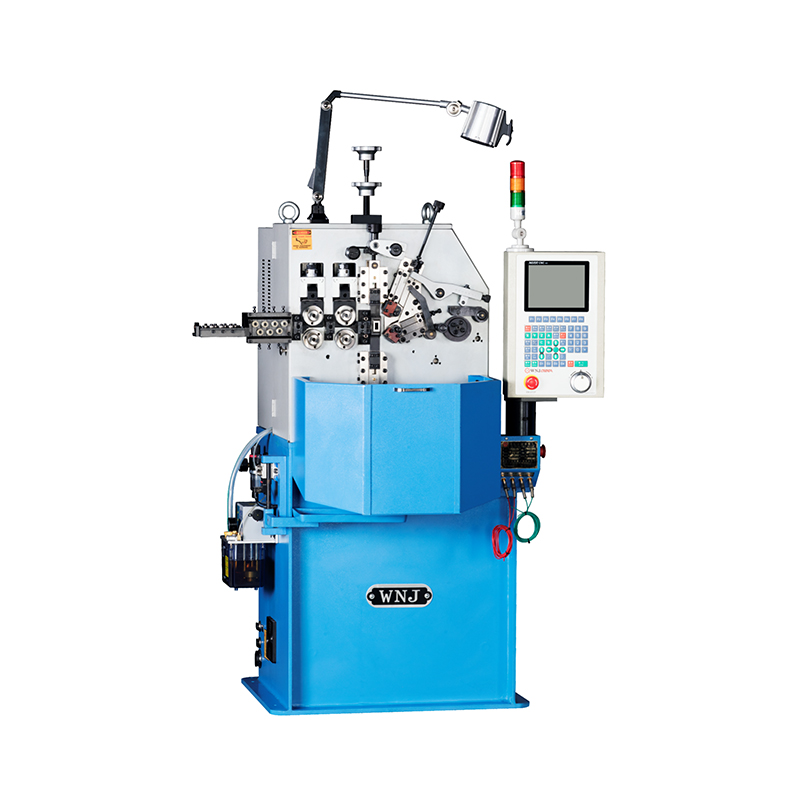 TK-320B 3-Axis CNC Spring Coiling Machine with Pitch ControlThis CNC coiler features independent pitch axis control and high-speed synchronous operation, making it ideal for producing compression springs with precise pitch and consistent wire feed, as highlighted in the preceding stress design discussion.View Product →
Compression spring tolerances are not just an afterthought. They decide whether the spring can be produced at acceptable cost and consistency. The table below shows typical tolerance levels that a CNC spring coiling machine can achieve in normal production.
| Parameter | Tolerance | Notes |
|---|---|---|
| Outer diameter | ±0.1 mm for d ≤ 3 mm | ±0.2 mm for larger wire |
| Free length | ±0.3 to ±0.5 mm | Depends on total coils |
| Spring rate | ±5% to ±10% | Affects load at deflection |
| Total coils | ±0.25 coils | Controlled by CNC feed |
| Squareness | 0.02 mm per 10 mm length | Measured against flat seat |
| Parallelism of ground ends | 0.05 mm | Requires grinding operation |
A tighter tolerance than these values is possible, but each reduction in tolerance range adds cost because it requires more inspection and setup time. Design for the widest tolerance that your application can accept, and specify the spring rate if the load at a certain deflection is what really matters.
The CNC spring coiling machine shown in this section is commonly used to produce compression springs with consistent pitch and wire feed. The ability to program the feed length and the number of coils precisely is what keeps the spring rate within a narrow band.
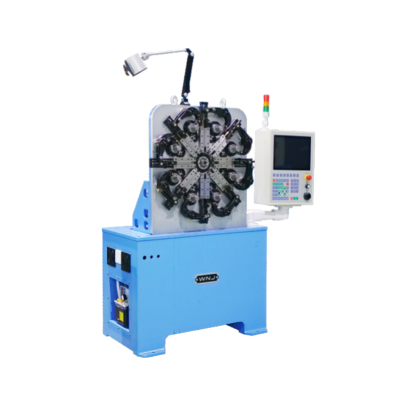 CNC-625D 4-Axis CNC Spring Forming Machine with DetectionEquipped with four axes and automatic detection, this forming machine stops on defects and allows parameter adjustments, ensuring repeatable production of various spring shapes, which supports the design-to-manufacturing continuity mentioned above.View Product →
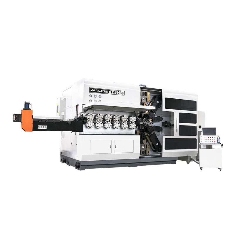
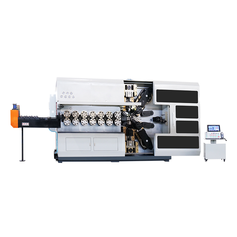
A compression spring design is only as good as the machine that forms it. CNC spring forming machines control the wire feed, the coiling pitch, the outer diameter, and the cut length electronically. This is why a design that is well-adapted to the equipment can be repeated thousands of times without drift.
The number of axes on a spring machine determines how complex a shape it can make. A 3-axis machine can produce standard compression springs, while a 5-axis or 10-axis machine can handle more advanced forms. If you want to understand the basic mechanics, read how does a CNC spring machine work. This helps you see why certain spring designs are easier to produce than others.
When a spring has a high spring index or a very small wire diameter, the machine needs accurate wire tension control. Otherwise, the pitch may vary along the spring length, causing an inconsistent rate. Pairing a realistic design with the right CNC forming machine is the fastest route to a stable production process.
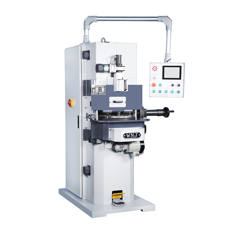 CNC Spring End Grinding Machine Series for Precision FinishingThis series offers CNC grinding with servo-controlled wheels and automatic inspection, suitable for grinding spring ends from 0.3 to 12mm wire, ensuring flatness and parallelism required before assembly in demanding applications.View Product →
The material of a compression spring is selected for the service environment and the required fatigue life. Common choices include carbon steel, oil-tempered spring steel, stainless steel, and alloy steels. For high-temperature or corrosive environments, stainless steel is often necessary, but it has a lower shear modulus and a different stress capacity.
After coiling, the spring has internal residual stresses that can reduce fatigue life. A spring temper furnace is used to stress-relieve the material and stabilize the dimensions. This step is not optional for high-performance springs. The heat treatment temperature is low enough to avoid changing the microstructure but high enough to relax the coiling stresses.
For springs with ground ends, a CNC spring grinding machine ensures that the end faces are flat and parallel. This improves the load distribution on the spring and prevents premature wear on the mating surface. The grinding operation is especially important when the spring is assembled in a compact cavity.
These mistakes show up again and again in new compression spring designs. Avoiding them will save you time and money.
This checklist helps you deliver a complete, manufacturable design to your spring manufacturer.
The spring rate is the most important value because it ties the load to the deflection. A correct spring rate means the spring will do its job in the assembly.
Start from the required stress and spring rate. A thicker wire makes the spring stiffer and increases stress for a given load, so the wire diameter must be balanced against the mean coil diameter and the number of active coils.
Spring index is the ratio of mean coil diameter to wire diameter. It should be in the range of 4 to 12. A low index increases internal stress and makes coiling hard; a high index makes the spring unstable and prone to buckling.
Yes. The spring rate is inversely proportional to the cube of active coils, so reducing active coils stiffens the spring. But you also need to keep the total coils and free length within practical limits.
Tempering relieves the residual stresses introduced by coiling. It stabilizes the spring dimensions and improves fatigue life. For most high-performance springs, this step cannot be skipped.
Specify the tightest tolerance that the function can justify, not the tightest the machine can hold. If the load at a given height is more important, tolerance the spring rate instead of the free length.
Compression spring design is a balance between calculations and practical production. The spring that works best on paper is not always the one that is easiest to make. By keeping the material, tolerances, and machine capabilities in view from the start, you can avoid common failures and get a spring that performs consistently for its entire service life.
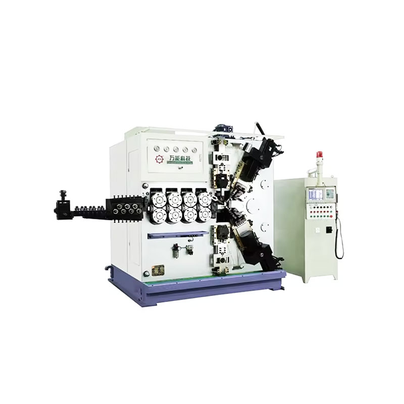
TK-6160 TK-6160 CNC SPRING ROLLING MACHINE...
See Details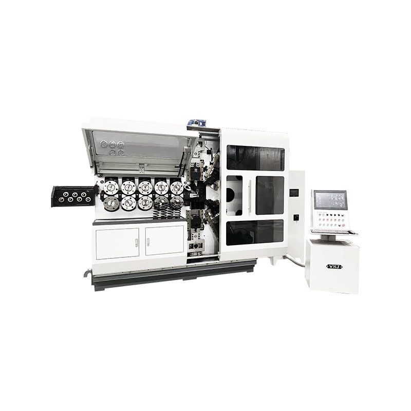
TK-6120 TK-6120 CNC SPRING ROLLING MACHINE...
See Details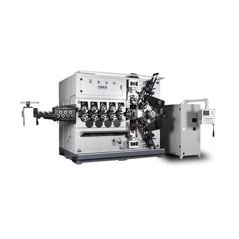
TK-5200 TK-5200 5AXES CNC SPRING COILING MACHINE...
See Details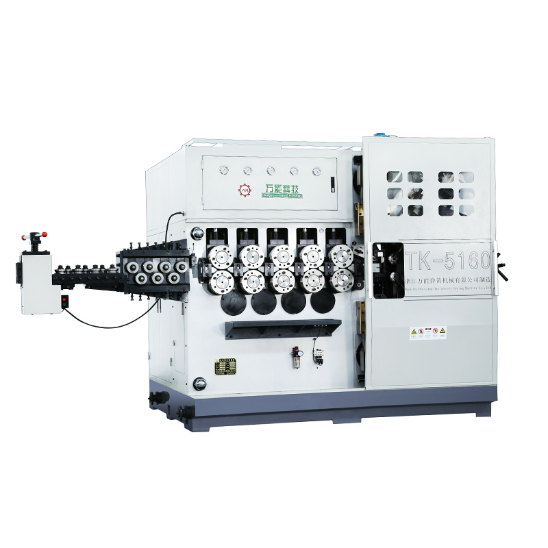
TK-5160 TK-5160 5AXES CNC SPRING COILING MACHINE...
See Details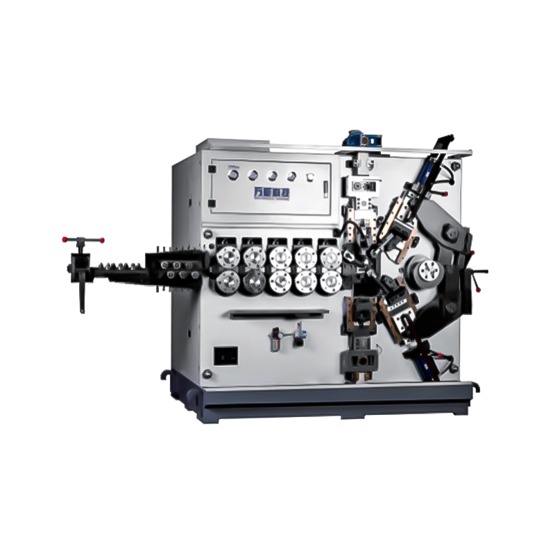
TK-5120 TK-5120 5AXES CNC SPRING COILING MACHINE...
See Details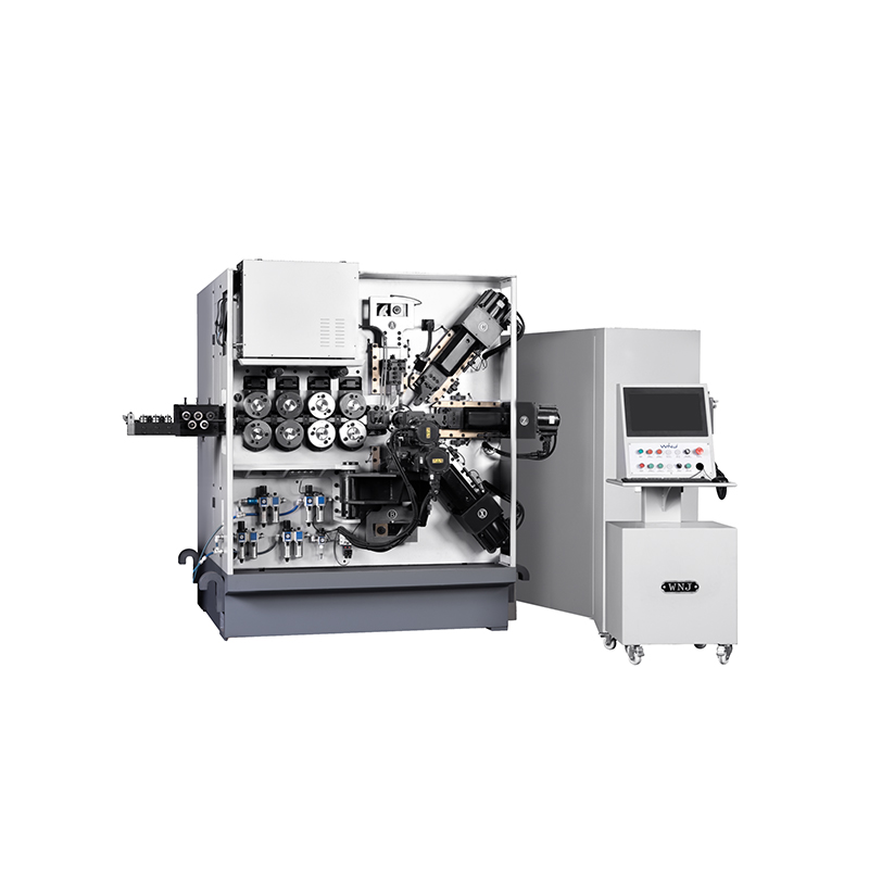
TK TK 10AXES CNC SPRING SCROLL MACHINE...
See Details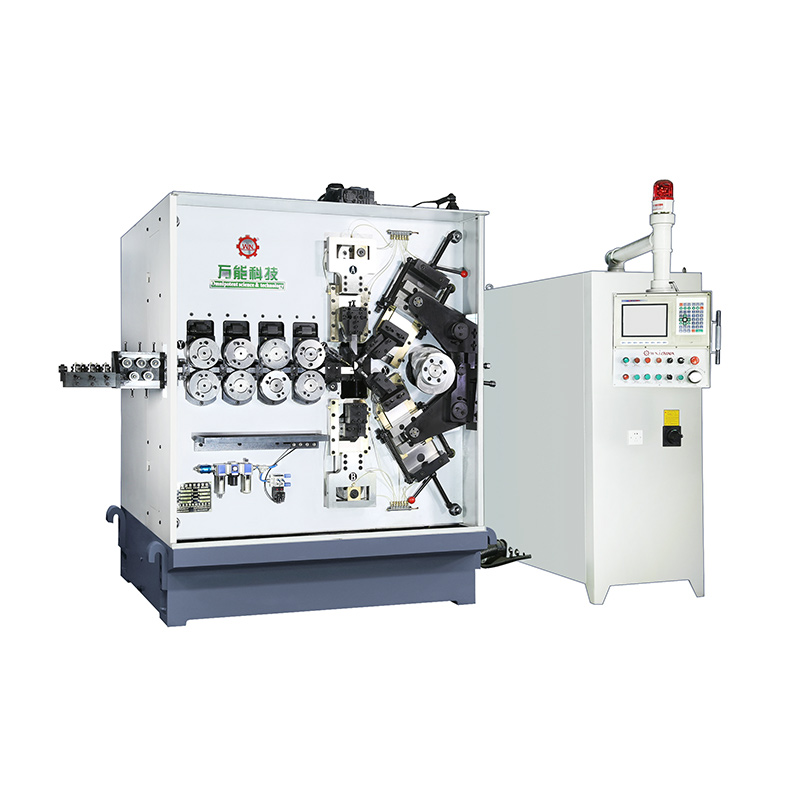
TK-580B、 TK-590 TK-580B、 TK-590 5AXES CNC SPRING COILING MACHINE...
See Details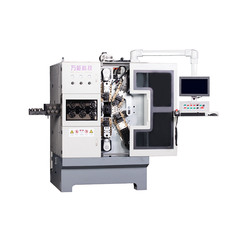
TK-760TK-760 6-7AXES CNC SPRING COILING MACHINE...
See DetailsMobile QR Code

 中文简体
中文简体 English
 русский
 Español