Language
Content
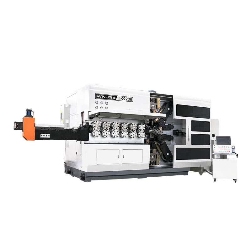
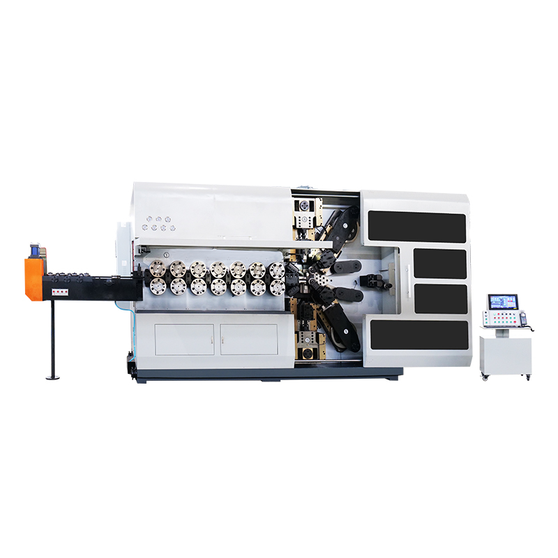
A CNC rod bender forms straight metal rod or wire into precise angles, loops, and multi-plane shapes by feeding stock through a set of rollers or dies while a servo-controlled bending head rotates around a programmed axis. The short answer to what makes it different from a manual or hydraulic bender is repeatability: once a bend program is saved, the machine reproduces the same angle, radius, and spring-back compensation on part 2 and part 20,000 without an operator resetting stops or guessing at overbend allowances.
This distinguishes a CNC unit from a general spring bending machine that relies on mechanical cams and fixed tooling profiles. Cam-driven machines are fast and inexpensive per unit output, but changing a shape means swapping physical cams and rebuilding the tool stack, often a half-day job. A CNC rod bender changes shape by loading a different program, typically a five to fifteen minute changeover depending on wire diameter and tooling complexity.
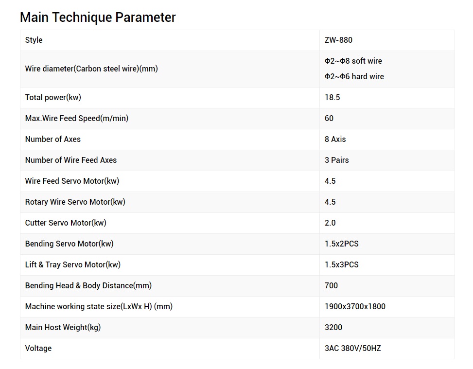
Every CNC rod bender, regardless of brand or wire diameter capacity, is built around five subsystems that work together to feed, straighten, and shape the material.
A bank of offset rollers removes coil-set from wire or rod before it reaches the bending head. Poorly adjusted straightening rollers are the single most common cause of inconsistent bend angles, since any residual curvature adds to or subtracts from the programmed bend.
A servo-driven feed roller pushes material forward in precise length increments, usually accurate to within 0.05mm on modern units, which determines the spacing between bends.
This head carries the bending pin and clamp die and rotates around the wire centerline. Multi-axis machines stack two or three of these heads to produce three-dimensional shapes in a single pass.
Servo motors replace older stepper or pneumatic drives on the bend axis, giving finer angular control and the torque feedback needed for real-time spring-back correction.
The touchscreen interface stores bend programs, displays wire counters, and lets an operator adjust a single bend angle mid-run without touching the rest of the sequence.
Shops running fewer than five distinct shapes a month, all in the same plane, often still find a dedicated cam-driven spring bending machine more economical. Once a production line runs eight or more shape variants, or any shape needs a bend outside a single plane, the changeover time saved by a CNC rod bender usually pays back the price difference within twelve to twenty months, depending on shift count.
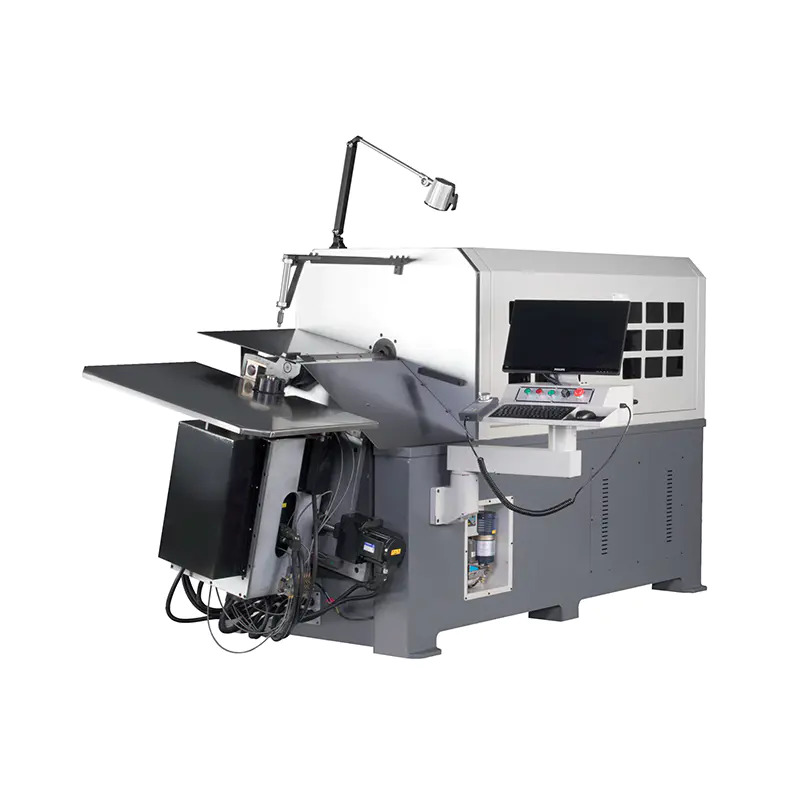
Machine spec sheets list a lot of numbers. These five actually predict whether a machine fits a given production job.
| Parameter | Typical Range | Why It Matters |
|---|---|---|
| Wire/rod diameter capacity | 0.5mm to 16mm | Sets which material range the machine can run without switching tooling families |
| Number of bending axes | 1 to 5 | More axes allow compound 3D shapes without repositioning the part |
| Feed speed | 0.5 to 3 meters per second | Directly drives parts-per-hour output for simple shapes |
| Bend angle resolution | 0.1° increments | Fine resolution matters for tight tolerance spring geometry |
| Program storage capacity | 50 to 500+ stored programs | Determines how many shape families can be recalled without reprogramming |
The same core bending technology shows up across very different end products, with the shape complexity and wire gauge driving which machine class fits best.
Seat frame wires, door lock rods, suspension clips, and torsion bar preforms
Mattress border rods, chair frame supports, shopping cart baskets
Refrigerator shelf racks, oven rack frames, dish rack wire forms
Surgical instrument wire guides and orthopedic rod preforms requiring tight angle tolerance
Rebar stirrups, mesh reinforcement clips, and structural tie rods
Display hooks, garment racks, point-of-sale wire stands
These three machine types are often confused because they all reshape wire, but each is built around a different core motion.
| Machine Type | Primary Motion | Best For |
|---|---|---|
| CNC rod bender | Rotary bend around fixed pin, multi-axis | Angular shapes, brackets, frames, multi-plane geometry |
| General wire forming machine | Combination of bend, cut, and slide motions | Complex small-diameter shapes like clips and springs with cut-off |
| Dedicated spring coiler | Continuous helical winding around a mandrel | Compression, extension, and torsion springs |
Selecting a machine comes down to matching five decision points to your actual part mix, in this order.
Shops that skip step two most often end up buying a single-axis machine that later cannot produce a shape a customer requests, forcing a second capital purchase within a year.
Most current CNC rod bender controllers use graphical, drag-and-node programming rather than manual G-code entry, letting an operator draw the target shape on the touchscreen and have the software calculate bend sequence, feed length, and rotation automatically.
Two software features separate a basic controller from a production-grade one. The first is automatic spring-back compensation, where the controller measures the actual bend angle after the tool retracts and adjusts the next cycle's overbend value without operator input. The second is simulation, where the software renders the finished shape in 3D before the first physical part is cut, catching collisions between the bending head and the part geometry that would otherwise damage tooling.
Wipe down straightening rollers and check for wire residue buildup, which changes friction and shifts bend angle over a shift.
Inspect the bending pin and clamp die for wear flats; a worn pin radius is the leading cause of drifting bend angle on machines running abrasive coated wire.
Check servo drive belt tension and backlash on the rotary bend axis, since accumulated backlash shows up as inconsistent angles only on direction reversals.
Recalibrate the feed length encoder against a known sample length, correcting for any drift introduced by roller wear.
| Defect | Likely Cause | Fix |
|---|---|---|
| Bend angle drifts over a run | Bending pin wear or heat buildup in the servo motor | Replace pin at first sign of a flat spot; verify motor cooling fan operation |
| Scratches or flat spots on wire surface | Misaligned straightening rollers or excessive clamp pressure | Realign roller stack; reduce clamp force to minimum needed to prevent slip |
| Inconsistent feed length | Feed roller slip on coated or oily wire | Increase roller grip texture or clamp pressure; clean oil residue from rollers |
| Shape twists out of plane | Uncompensated torsional spring-back on high-tensile wire | Add a small counter-rotation step in the program before the main bend |
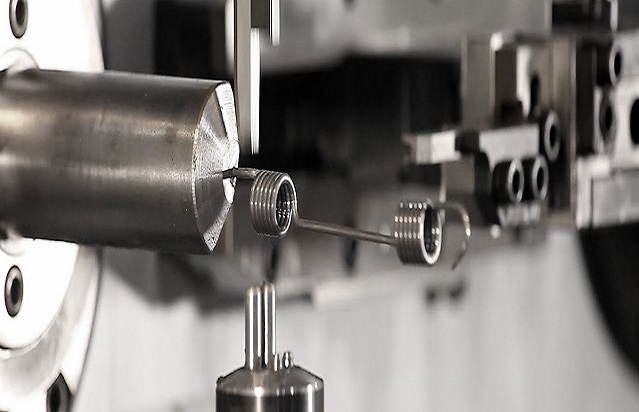
Typical reduction in changeover labor time after switching from cam-driven to CNC bending for shops running six or more shape variants
Months of payback period for a mid-size CNC rod bender at two-shift operation with frequent shape changes
Typical scrap rate reduction once automatic spring-back compensation replaces manual overbend guessing
Beyond the purchase price, the ongoing cost drivers worth budgeting for are tooling wear parts (bending pins, clamp dies), annual servo maintenance, and operator training time, which usually runs one to two weeks for a technician already familiar with manual bending equipment.
Three developments are showing up across newer machine generations rather than remaining lab concepts.
Closed-loop angle sensing now measures the actual bend in real time using inline encoders rather than relying only on pre-calculated spring-back tables, cutting first-article scrap on new materials.
Remote diagnostics let a machine builder review controller logs over a network connection to diagnose a fault before sending a technician, shortening downtime on complex servo faults.
Modular tooling cartridges that swap bending pin, clamp die, and cutting blade as a single preset unit are cutting changeover time on multi-axis machines from fifteen minutes down toward three to five minutes.
Most production machines cover a range within their class, commonly 0.5mm to 6mm on light-duty units and up to 16mm on heavy-duty rod benders built for rebar or structural applications. A single machine rarely covers the full range well, so matching the machine class to your actual material range matters more than looking at the widest number on a spec sheet.
Loading a saved program from memory typically takes under a minute. The longer step is physical tooling changeover if the new shape needs a different bending pin or clamp die, which usually adds five to fifteen minutes depending on tooling design.
Not exactly. Spring bending machine is a broader term that includes cam-driven, hydraulic, and CNC-controlled equipment. A CNC rod bender is one category within that broader group, distinguished by servo-driven, program-based control rather than mechanical cams.
Spring-back is the material's elastic recovery after the bending force is removed, causing the final angle to open up slightly from the angle set during forming. Higher tensile materials spring back more. CNC controllers compensate by overbending a calculated amount, then measuring and adjusting that value automatically on later cycles.
Within a limited range, yes, since the clamp die and straightening rollers usually accept a band of diameters with minor adjustment. Moving to a significantly different diameter, for example from 2mm to 8mm, typically requires a different tooling set matched to that thicker material.
Simple single-plane brackets only need one bending axis. Shapes with bends in more than one plane, such as a three-dimensional wire frame, need two or three axes to avoid repositioning the part manually between bends, which reintroduces the accuracy problems CNC bending is meant to solve.
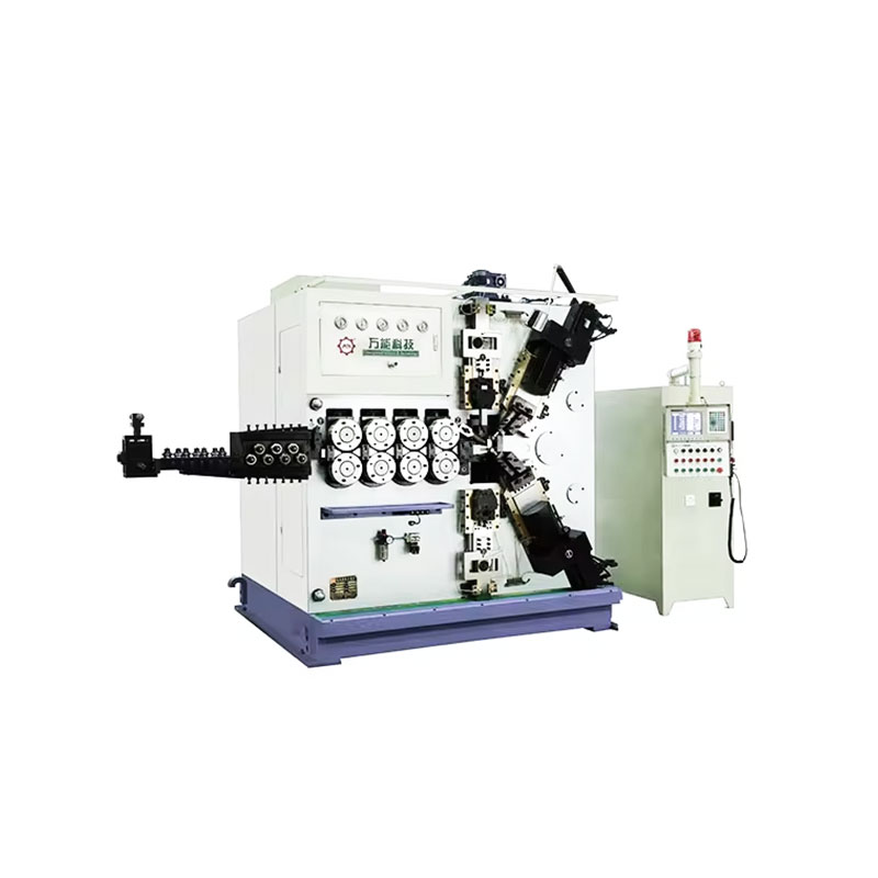
TK-6160 TK-6160 CNC SPRING ROLLING MACHINE...
See Details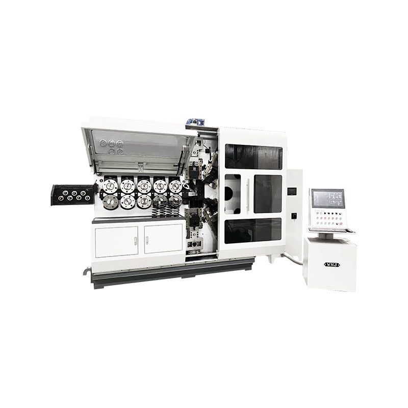
TK-6120 TK-6120 CNC SPRING ROLLING MACHINE...
See Details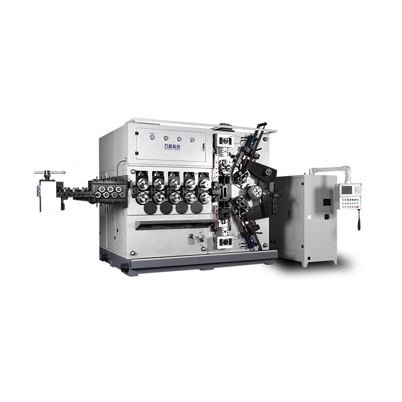
TK-5200 TK-5200 5AXES CNC SPRING COILING MACHINE...
See Details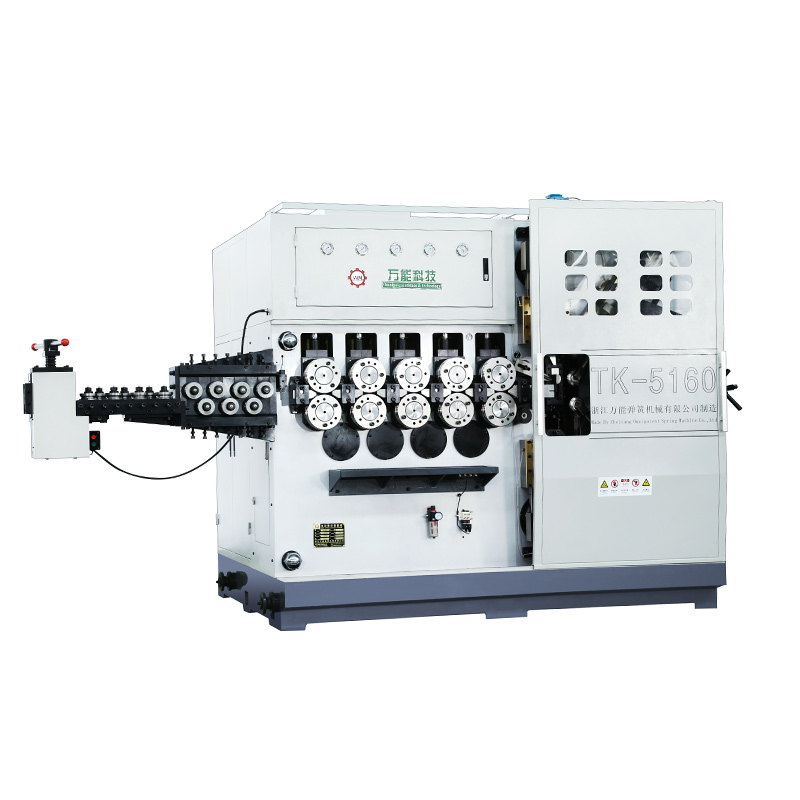
TK-5160 TK-5160 5AXES CNC SPRING COILING MACHINE...
See Details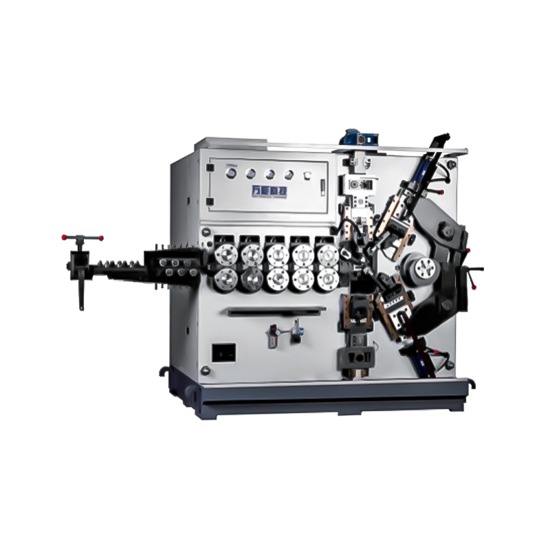
TK-5120 TK-5120 5AXES CNC SPRING COILING MACHINE...
See Details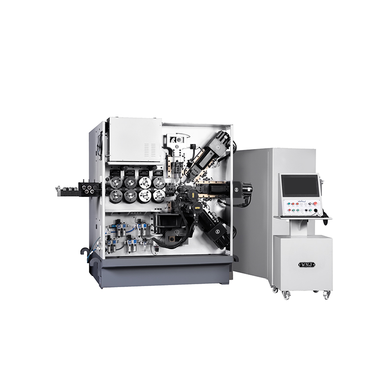
TK TK 10AXES CNC SPRING SCROLL MACHINE...
See Details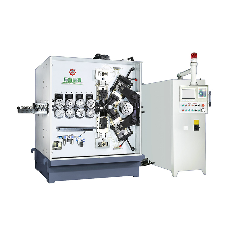
TK-580B、 TK-590 TK-580B、 TK-590 5AXES CNC SPRING COILING MACHINE...
See Details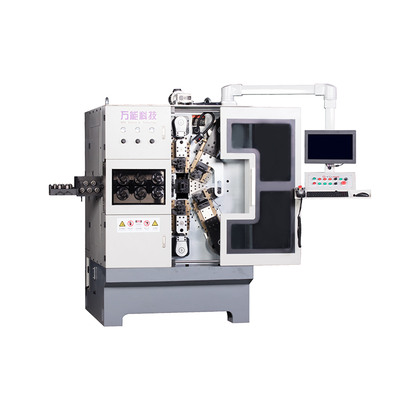
TK-760TK-760 6-7AXES CNC SPRING COILING MACHINE...
See DetailsMobile QR Code

 中文简体
中文简体 English
 русский
 Español