Content
Bending metal wire is not a single process — it is a category of precision manufacturing operations that varies significantly depending on wire material, diameter, required geometry, and production volume. The short answer: for low-volume or craft applications, manual tools and simple jigs get the job done; for industrial-scale production, a dedicated spring bending machine or CNC wire forming machine is the only viable path to consistent quality and cost efficiency.
Understanding the mechanics behind bending metal wire correctly from the start prevents the most common and expensive mistakes — springback miscalculation, surface cracking, work hardening failures, and dimensional inconsistency across batches. This article covers material behavior, tooling selection, machine types, process parameters, and quality control, with concrete data drawn from industry practice.
Every metal wire bending operation involves two competing phenomena: elastic deformation and plastic deformation. The elastic zone springs back when force is released; the plastic zone retains the new shape. The ratio between the two determines how much "over-bend" is required to hit a target angle — a critical calculation for any precision component.
Springback occurs because the outer fibers of a bent wire pass through elastic deformation and partially recover after the bending tool releases. The magnitude of springback depends on three variables:
In practical terms, a 1.2 mm stainless steel wire bent to a 90° angle may require a 97°–103° tool angle to compensate for springback, depending on temper. A modern CNC spring bending machine accounts for this automatically through closed-loop angle compensation, but manual or semi-automatic setups require the operator to dial in the correction empirically.
Attempting to bend metal wire below its minimum bend radius causes cracking on the outer surface or buckling on the inner surface. The table below provides reference values for commonly used wire materials:
| Material | Condition | Min. Bend Radius (× wire diameter) | Typical Springback (90° bend) |
|---|---|---|---|
| Soft copper | Annealed | 0.5×d | 2°–4° |
| Mild steel (low carbon) | Annealed | 1.0×d | 4°–7° |
| Stainless steel 304 | 1/2 Hard | 2.0×d | 8°–14° |
| Music wire (high carbon) | Hard drawn | 2.5×d | 10°–18° |
| Aluminum 1100 | Soft | 0.5×d | 3°–5° |
| Titanium Grade 2 | Annealed | 3.0×d | 15°–25° |
These figures underscore why wire material selection happens before tooling selection — not after. A spring bending machine set up for low-carbon steel wire will produce out-of-tolerance parts if the operator switches to stainless steel without recalibrating the bend angle and tooling geometry.
Wire diameter is the single most decisive factor in equipment selection. The bending force required scales with the cube of the wire diameter, which means doubling the diameter increases the required bending torque roughly eightfold. A machine rated for 1.5 mm wire cannot simply "push harder" to bend 3 mm wire — the tool geometry, feed mechanism, and drive system all operate in different regimes.
Fine wire bending below 1.0 mm diameter is used in medical devices, precision electronics, and micro-spring manufacturing. At this scale, surface finish and lubrication become critical because even microscopic tool wear changes the bend geometry. Micro-spring bending machines in this range typically operate at wire tensions under 5 N and require hardened carbide tooling to maintain dimensional stability across production runs of 50,000+ pieces.
Feed accuracy requirements are also extreme: a 0.5 mm wire component with a 10 mm leg length needs feed repeatability within ±0.05 mm to stay within a ±0.5% length tolerance. Servo-driven feed systems on CNC spring forming machines achieve this consistently; manual feed mechanisms cannot.
This is the most common diameter range for general-purpose wire bending, encompassing compression springs, torsion springs, wire forms, clips, and hooks used in automotive, appliance, and furniture manufacturing. A spring bending machine designed for this range is the backbone of most wire forming shops.
A well-configured CNC wire bending machine in this range can produce 60–200 parts per minute, depending on part complexity and the number of bend operations per cycle. A 2.0 mm steel wire torsion spring with 8 coils and two legs typically runs at 80–120 ppm on a 4-axis CNC coiling machine.
Heavy wire bending approaches the territory of rebar forming and structural wire processing. Machines in this range use hydraulic or heavy-duty servo drives to generate the bending forces required. Production speeds are lower (10–40 ppm), but part weights and structural demands are far greater. Rebar bending machines, for example, routinely process 8 mm to 12 mm steel rod at bending forces exceeding 2,000 N.
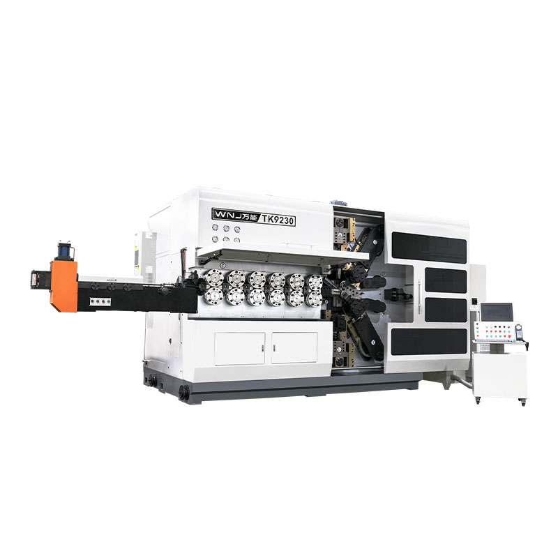
The term "spring bending machine" is used broadly in the industry to refer to any automated or semi-automated machine that bends metal wire into spring or wire form shapes. In practice, there are several distinct machine architectures, each optimized for different part geometries and production requirements.
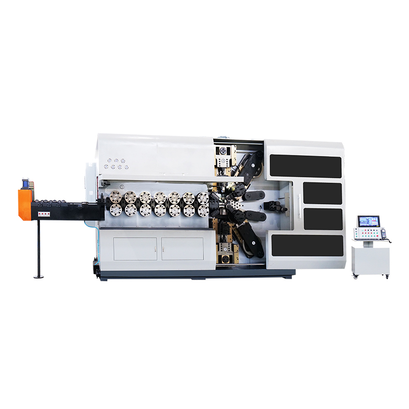
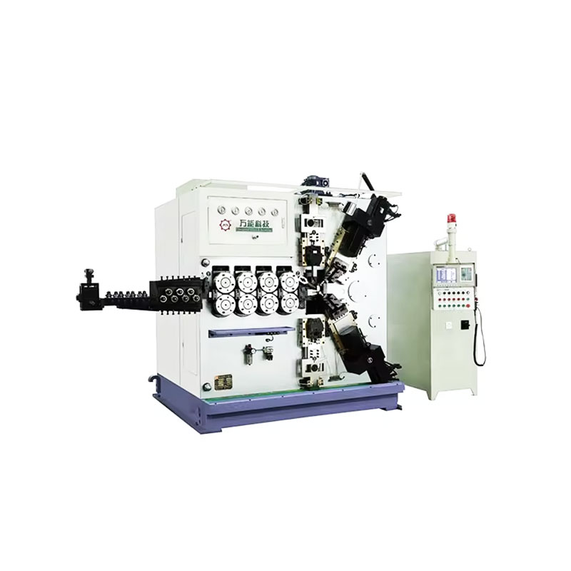
CNC spring coiling machines are the most widely deployed type of spring bending machine for compression and extension spring production. The wire is fed through a straightening section, then guided over a coiling point while a pitch tool controls the spacing between coils. The entire process — coil diameter, pitch, leg length, end type — is programmed through a CNC controller.
Modern CNC coiling machines typically have 2–4 controlled axes. Entry-level machines control wire feed and coiling point position; advanced models add independent pitch control and a cutting axis for precise end geometry. High-end CNC coiling machines can store 500+ part programs and switch between them in under 3 minutes, making them highly efficient for shops running multiple SKUs.
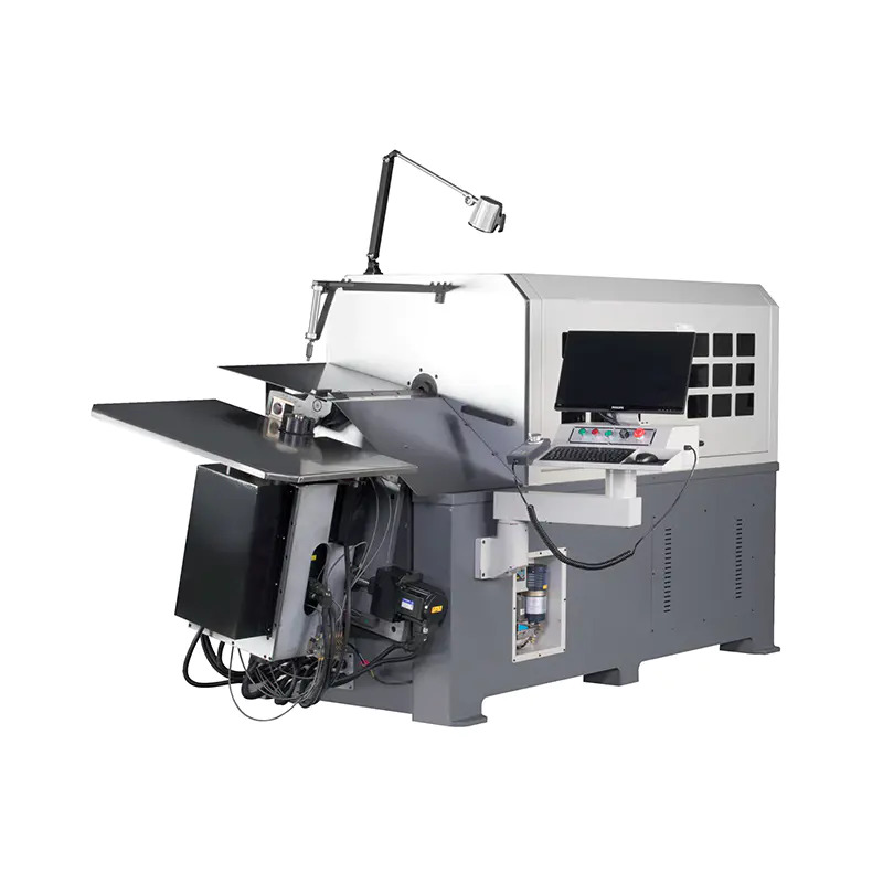
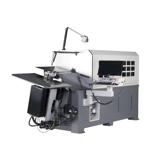
Wire forming machines are the more versatile cousin of coiling machines. Where a coiling machine excels at helical shapes, a wire forming machine can produce 2D and 3D wire forms with multiple bends, loops, hooks, and offsets — all in a single continuous operation from coil stock.
The number of axes on a wire forming machine directly corresponds to the complexity of parts it can produce:
A 6-axis CNC wire forming machine capable of handling 0.3–3.5 mm wire typically costs between $80,000 and $200,000 USD, depending on axis count, wire diameter capacity, and controller sophistication. The investment is justified when annual production volume exceeds approximately 500,000 pieces or when part geometry cannot be achieved manually.
Torsion springs require a dedicated machine architecture because the leg forming operation happens at a specific angular position relative to the coil body. Torsion spring bending machines use a coordinated sequence: coil the body, stop at the correct angular position, then bend each leg to the programmed angle. Getting this angular timing wrong by even 5° produces a part that generates the wrong torque at the design deflection point — a critical failure mode in automotive door hinges, for example, where torsion springs must meet torque tolerances of ±5%.
Not every application requires a full CNC spring bending machine. For prototype quantities (under 500 pieces), repair operations, or custom fabrication with complex geometry that changes frequently, semi-automatic benchtop wire benders and manual jig-based bending tools are practical. These machines use a fixed mandrel and a rotating forming arm to produce consistent bend angles without CNC programming. Repeatability is lower (typically ±2°–5° vs. ±0.5° for CNC), but setup time is measured in minutes rather than hours.
Regardless of whether the operation is manual or fully automated on a CNC spring bending machine, the same fundamental process parameters determine part quality. Controlling these parameters consistently is the difference between a stable process and one that generates scrap at random intervals.
Wire feed speed must be matched to the bending operation cycle time. Too fast, and wire piles up at the bending station, causing misfeeds and tangles. Too slow, and productivity suffers unnecessarily. Most CNC coiling machines run wire feed speeds between 50 mm/s and 400 mm/s, with the upper end reserved for simple geometries in soft wire materials.
Wire back tension — the resistance in the coil payoff system — has a direct effect on coil diameter consistency. Higher back tension slightly reduces the coil diameter because the wire is under tension as it contacts the coiling tool. A change in back tension of just 2–5 N can shift coil diameter by 0.1–0.3 mm on a 2 mm wire, which is significant for springs with tight free-length or load tolerances.
CNC-controlled spring bending machines achieve bend angle repeatability through one of two methods: open-loop angle control (the tool moves to a fixed programmed position) or closed-loop control with angle measurement feedback. Open-loop systems are adequate for soft materials with predictable springback, but for high-strength wire or applications where ±1° tolerance is required, closed-loop systems with in-process measurement are necessary.
Some advanced wire forming machines use vision systems or laser measurement to check the bent angle on each part and automatically adjust the tool position for the next cycle. This adaptive correction eliminates drift caused by tool wear or gradual changes in wire mechanical properties across a coil.
Wire bending is a frictional process — the wire slides against bending tools, guides, and straightening rollers during every cycle. Without adequate lubrication, three problems develop: accelerated tool wear, surface scratches on the wire, and heat buildup that changes the wire's mechanical properties during a long production run.
For most steel wire bending operations, a light mineral oil or synthetic wire drawing lubricant applied at the payoff or straightener is sufficient. Stainless steel wire may require a chlorine-free synthetic lubricant to prevent chloride-induced stress corrosion cracking. Copper wire typically needs minimal lubrication because of its inherently low friction properties.
Wire fed from a coil carries residual curvature (cast) and helical twist (helix). Both must be eliminated before the wire enters the bending zone, or the resulting parts will have inconsistent geometry and poor dimensional repeatability. Straightening is done with a series of offset rollers — typically 5 to 7 rollers in two planes, set at a slight interference angle to plastically deform and re-straighten the wire.
Under-straightening leaves residual cast, causing coil diameter variation. Over-straightening work-hardens the wire surface, increasing springback and reducing ductility at bend points. Getting the straightener setting right for each wire lot is a non-negotiable first step on any spring bending machine.
The range of industries that depend on precision metal wire bending is far broader than most people realize. A single modern automobile contains between 300 and 700 individual wire springs and wire forms. Understanding which industries drive demand helps clarify why consistent bending quality is so economically important.
Automotive is the largest consumer of precision-bent wire forms globally. Applications include seat recline springs, door handle return springs, brake pad anti-rattle clips, windshield wiper linkage clips, engine hose clamps, and dozens of valve spring variants. Tolerances are tight: a seat recline spring might require a free-length tolerance of ±0.5 mm and a load tolerance of ±8% at a defined deflection. Only a calibrated spring bending machine running a validated program consistently meets these requirements at production volumes of millions per year.
Medical wire bending operates at the intersection of extreme precision and strict material traceability requirements. Guidewires, stent frames, surgical clip closures, and implantable spring contacts all require wire bending to tolerances measured in microns, from materials like nitinol, 316L stainless steel, or platinum-iridium alloy. Nitinol (nickel-titanium alloy) is particularly challenging because it combines superelastic behavior with a strong temperature dependence — bending it at room temperature and bending it at body temperature (37°C) produces different final geometries without accounting for its shape-memory properties.
Battery contacts, connector springs, terminal clips, and grounding springs are all produced by bending metal wire or strip. Beryllium copper and phosphor bronze are the preferred materials in this sector because they combine high electrical conductivity with excellent spring properties. Contact force — the force a bent spring contact exerts on a mating surface — must be held within ±15% to ensure reliable electrical connection without damaging the mating component.
Mattress spring units, sofa frame springs, bicycle basket wire frames, clothes hangers, and display rack hooks are all high-volume wire bending products where cost per piece drives machine selection. In this segment, production speed takes priority over ultra-tight tolerances. A wire forming machine producing 50 million mattress Bonnell spring units per year for a single customer needs maximum uptime and minimum changeover time — not micron-level accuracy.
Aerospace wire bending combines the tight tolerances of medical with the volume demands of automotive — but adds regulatory documentation requirements that other industries do not face. Every wire form used in flight-critical systems must be traceable to certified material, manufactured on calibrated and validated equipment, and inspected to AS9100 standards. A spring bending machine used in aerospace production carries a full calibration history and process validation record.
Choosing a spring bending machine is not a catalog-browsing exercise. The right machine depends on a specific combination of part requirements, production volume, material, and budget. The following framework addresses the decision in a logical sequence.
Every spring bending machine has a rated wire diameter range, and operating at the edges of that range reduces machine life and part quality. Select a machine whose rated midpoint matches your most common wire diameter. If your product mix spans 0.5 mm to 3.0 mm, consider two smaller machines rather than one machine running at its upper limit for large-diameter wire and its lower limit for fine wire.
A simple compression spring with straight ends needs only a 2-axis CNC coiling machine. A torsion spring with offset legs in two planes needs at least 4 axes. A complex 3D wire form with multiple bend planes and a closed loop end requires 6–8 axes. Overbuying axis count adds cost without benefit; underbuying creates geometric limitations that cannot be worked around.
This is the most direct justification driver for automation level and machine investment. Use the following rough benchmarks:
The CNC controller is the brain of any spring bending machine. Key features to evaluate include: part program storage capacity, simulation mode (allows testing a new program without running wire through the machine), springback compensation settings, production counter and fault logging, and compatibility with offline programming software. Manufacturers like Wafios, Simplex, and Numalliance offer proprietary controllers with spring-specific simulation tools that reduce first-article setup time from hours to 20–40 minutes for experienced operators.
Machine price is only part of the total investment. Tooling — bending pins, coiling points, mandrels, cutoff tools — adds $5,000–$30,000 for a fully tooled machine, and lead times for custom tooling can reach 4–8 weeks. Factor this into project timelines for new part launches, especially when machine delivery and tooling delivery are from separate suppliers.
Quality control for bent metal wire goes beyond measuring a few pieces at the start of a shift. Consistent quality requires in-process monitoring, statistical control, and a clear sampling plan that matches the risk level of each dimension.
For springs, the critical dimensions are typically: free length, coil diameter (inside or outside), number of active coils, end type geometry, and load at a specified deflection. For wire forms, critical dimensions include overall length, bend angles, loop diameters, and hole or slot positions. Functional dimensions — those that directly affect fit, function, or safety — should be measured on every part or at a minimum every 500th part, depending on process capability.
A minimum Cpk of 1.33 is the standard requirement for most automotive wire spring applications, meaning the process mean is at least 4 standard deviations from the nearest specification limit. Achieving Cpk ≥1.67 is required by some Tier 1 automotive customers for safety-critical springs. Reaching these targets requires both a capable spring bending machine and rigorous incoming material control — wire mechanical property variation from coil to coil is often the largest single source of dimensional scatter in production.
Even on a well-configured spring bending machine with an experienced operator, wire bending defects appear. Knowing how to diagnose and correct them quickly reduces scrap and downtime.
| Defect | Likely Cause | Corrective Action |
|---|---|---|
| Coil diameter drifting large | Decreasing back tension; tool wear | Check payoff brake; measure coiling pin wear |
| Coil diameter drifting small | Increasing back tension; over-straightening | Reduce straightener pressure; check payoff tension |
| Surface cracking at bend | Radius too tight; work-hardened material; wrong material | Increase bend radius; verify wire temper; anneal if needed |
| Inconsistent bend angles | Springback variation; loose tool mounting | Enable springback compensation; inspect tool clamps |
| Misfeed / wire jamming | Feed roll pressure incorrect; guide wear; cast residual | Adjust feed rolls; replace worn guides; optimize straightener |
| Pitch inconsistency (springs) | Pitch tool wear; variable feed speed | Replace pitch tool; check servo drive response |
| Burrs at cut-off point | Dull cutter; incorrect cutting clearance | Sharpen or replace cutter; adjust cutting gap |
Systematic defect logging is essential. When a defect recurs across multiple lots, the root cause is almost always material variation or tool wear — both of which are predictable and preventable with proper maintenance schedules and incoming material qualification procedures.
Bending is typically not the final operation. Depending on the application, bent metal wire components undergo one or more finishing steps that affect appearance, corrosion resistance, fatigue life, and friction properties.
Shot peening introduces compressive residual stresses into the wire surface, which counteracts the tensile stresses that initiate fatigue cracks during cyclic loading. For automotive valve springs and high-cycle torsion springs, shot peening can increase fatigue life by 30–100% compared to unpeened counterparts. The process is standard practice for springs with design lives above 500,000 cycles.
After bending metal wire, residual stresses remain at the bend points from the forming operation. For precision springs, these stresses cause slow dimensional change over time (stress relaxation) unless the springs are heat-set. Heat setting involves loading the spring to its solid height or a defined compressed position and holding it at 150°C–250°C for 20–30 minutes. This process stabilizes the free length to within ±0.2 mm and significantly reduces in-service relaxation.
Zinc plating (electrogalvanizing) is the most common corrosion protection for steel wire forms in non-critical applications. A 5–8 µm zinc layer provides adequate protection for indoor applications or moderate outdoor exposure. For harsher environments, zinc-nickel alloy plating (12–15% nickel content) offers 5–10× better corrosion resistance. Stainless steel and copper wire typically do not require plating. Plastic coating — PVC dip or nylon powder coating — is used for wire forms that require electrical insulation or where metal contact could damage a mating component.
Wire bending technology is not static. Several developments are changing how spring bending machines are designed, programmed, and integrated into manufacturing environments.
Programming a spring bending machine historically required running wire through the machine in trial-and-error iterations until the geometry matched the print. Modern offline programming software simulates the bending process in 3D, predicting springback, tool collisions, and geometric deviations before a single piece of wire is consumed. Wafios's FMU software and Numalliance's Spring CAM, for example, reduce first-article setup time by 40–60% compared to manual programming methods, according to industry user reports.
Machine learning algorithms are beginning to appear in wire bending process control. These systems collect sensor data — bend force profiles, feed speed variations, temperature — and use this data to predict when tool wear will begin affecting part quality, triggering maintenance alerts before defects appear. Early implementations report a 20–35% reduction in unplanned downtime on high-volume spring bending lines.
As product mix increases and batch sizes decrease, changeover time on a spring bending machine has become a competitive differentiator. Quick-change tooling systems using precision ground tool holders with repeatable locating features allow an experienced operator to switch a machine from one part number to another in 15–30 minutes, compared to 2–4 hours with traditional tooling. This is particularly valuable for contract spring manufacturers running 50+ different part numbers per week.
Lightweighting pressure in automotive and the miniaturization trend in electronics are pushing wire bending into increasingly difficult materials. High-strength valve spring wire with tensile strengths above 2,200 MPa, superelastic nitinol at room temperature, and cobalt-chromium alloys for medical implants all require machines with higher force capacity, harder tooling materials, and more sophisticated springback compensation than were standard five years ago. The market for advanced wire forming machines capable of handling these materials is growing at approximately 6–8% annually, driven primarily by electric vehicle and medical device demand.
TK-6160 TK-6160 CNC SPRING ROLLING MACHINE...
See Details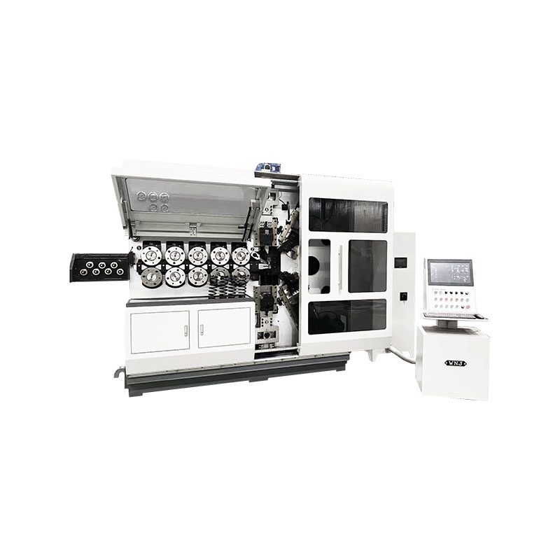
TK-6120 TK-6120 CNC SPRING ROLLING MACHINE...
See Details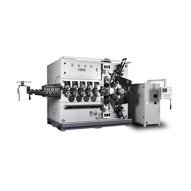
TK-5200 TK-5200 5AXES CNC SPRING COILING MACHINE...
See Details
TK-5160 TK-5160 5AXES CNC SPRING COILING MACHINE...
See Details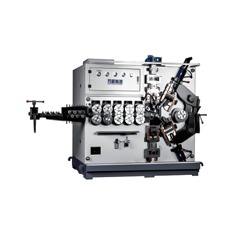
TK-5120 TK-5120 5AXES CNC SPRING COILING MACHINE...
See Details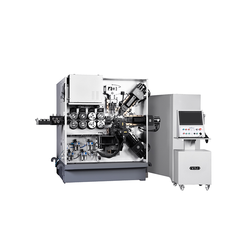
TK TK 10AXES CNC SPRING SCROLL MACHINE...
See Details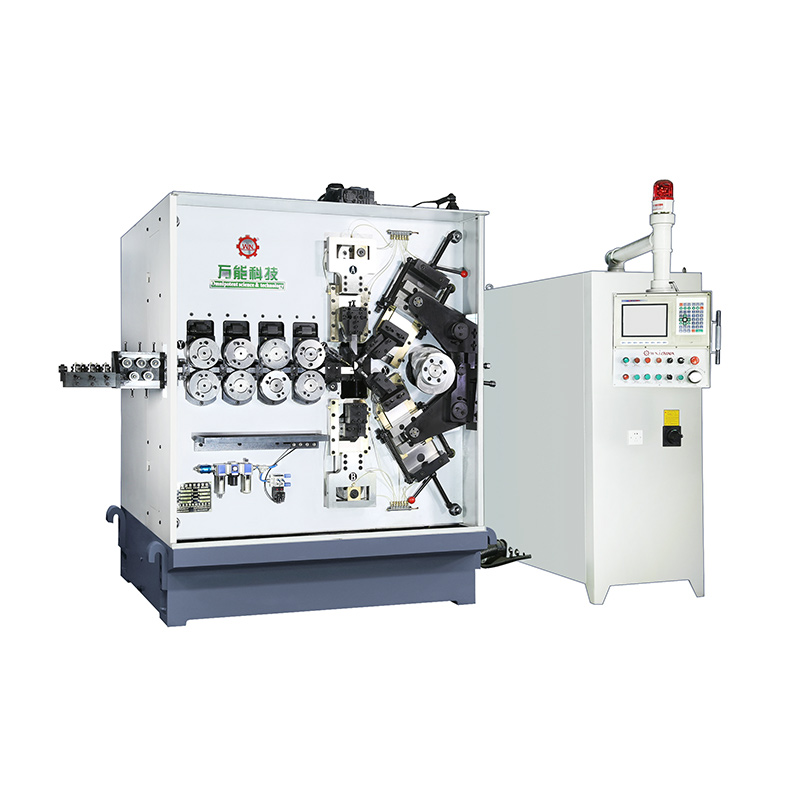
TK-580B、 TK-590 TK-580B、 TK-590 5AXES CNC SPRING COILING MACHINE...
See Details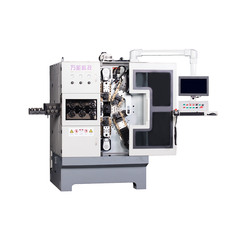
TK-760TK-760 6-7AXES CNC SPRING COILING MACHINE...
See DetailsMobile QR Code

 Language
  中文简体
中文简体 English
 русский
 Español