Content
A bending metal machine is industrial equipment designed to deform metal workpieces — sheets, bars, tubes, or wire — into precise angles, curves, or complex three-dimensional shapes without cutting or welding. The core conclusion is straightforward: if your production line requires consistent, repeatable metal shapes at scale, a dedicated bending machine is not optional equipment — it is the backbone of your workflow. Manual bending introduces human error, inconsistent bend radii, and operator fatigue; mechanized bending eliminates all three.
Modern metal bending machines range from simple hydraulic press brakes capable of bending 3 mm mild steel plate to sophisticated CNC multi-axis systems that can execute 40 distinct bend sequences in a single automated cycle. A mid-range CNC press brake, for instance, can achieve angular repeatability of ±0.1°, which is essentially unattainable through manual operation. For automotive brackets, HVAC ductwork, furniture frames, electrical enclosures, and hundreds of other product categories, this level of precision is not a luxury — it is a manufacturing requirement.
The spring bending machine is a specialized subset of the broader bending machine family. While a general press brake focuses on sheet metal, a spring bending machine is engineered specifically to wind, coil, and form wire or rod stock into compression springs, extension springs, torsion springs, and custom wire forms. These two machine types often coexist in the same facility — and understanding how they complement each other is essential for any fabrication manager sourcing equipment.
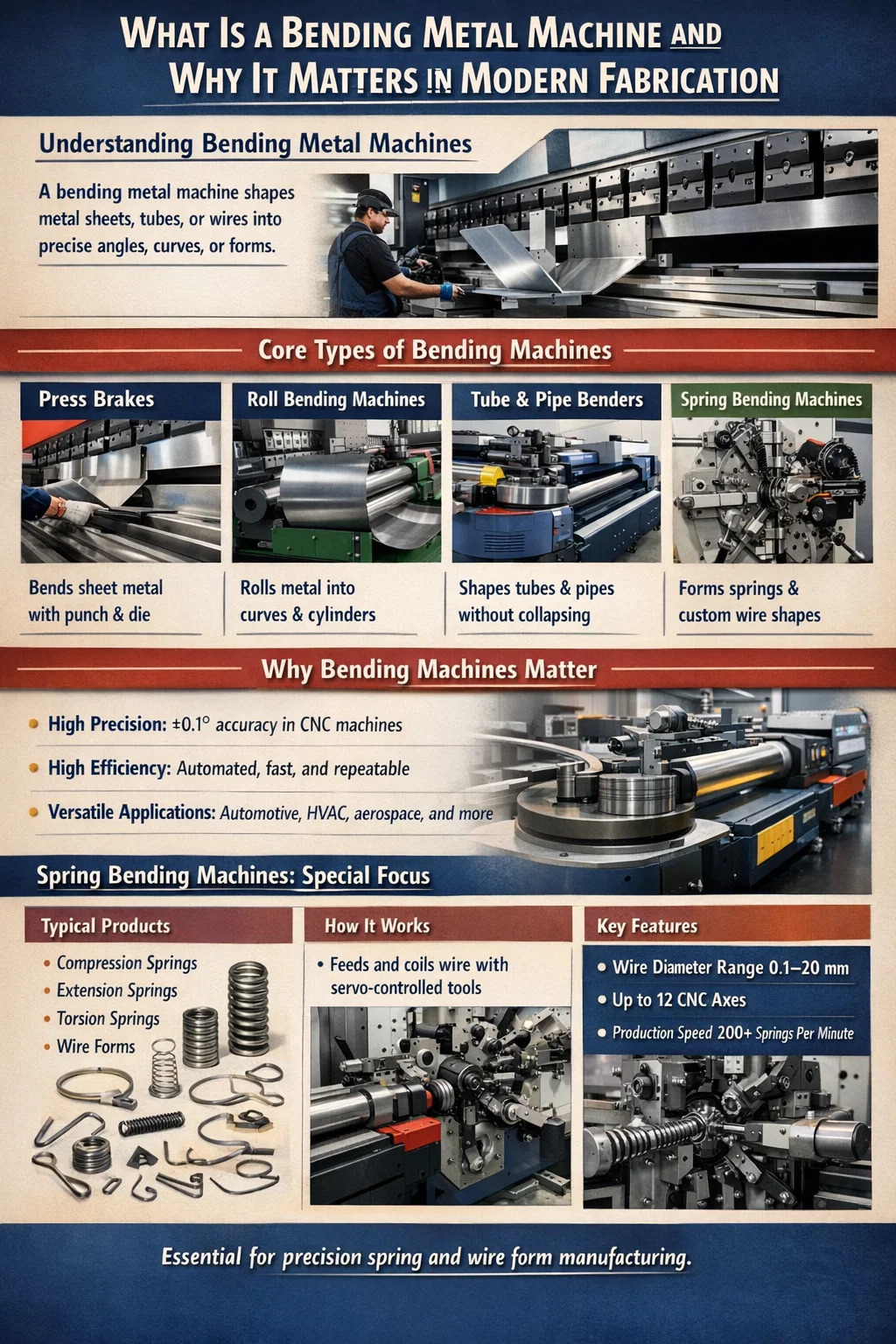
The term "bending metal machine" is an umbrella covering several distinct machine architectures. Choosing the wrong type for your application leads to poor part quality, excessive tooling wear, and unnecessary capital expenditure. Below is a structured breakdown of the main categories.
The press brake is the most widely deployed sheet metal bending machine globally. It uses a punch and die set to apply localized force along a straight line, creating a single bend per stroke. Hydraulic press brakes dominate heavy-duty applications — bending steel plate up to 25 mm thick across bending lengths of 6 meters or more. Electric servo press brakes, increasingly popular since 2018, offer energy savings of 30–50% compared to hydraulic counterparts and provide faster cycle times for thin-gauge work (0.5–3 mm). CNC press brakes add programmable back-gauge positioning, automatic crowning compensation, and multi-step bend sequencing, reducing setup time from hours to minutes when switching between part programs.
Roll bending machines — also called plate rollers or section benders — use two or three driven rolls to continuously curve metal into arcs, rings, or cylinders. They are indispensable for pressure vessel manufacturing, pipe production, architectural steelwork, and tank fabrication. A three-roll symmetrical machine is the standard for producing large-diameter cylinders from flat plate. A four-roll machine adds a fourth roll that pre-bends the leading edge, eliminating the flat spot that is the classic limitation of three-roll designs. Bending radii from tight 150 mm curves to gentle arcs spanning several meters are achievable depending on machine tonnage and roll diameter.
Tube bending machines bend hollow sections — round, square, or rectangular tubing — without collapsing the cross-section. Rotary draw bending, the most precise method, clamps the tube against a form die and rotates it around a fixed bend die, often with an internal mandrel preventing wall collapse. This method is standard in automotive exhaust systems, roll cages, bicycle frames, and aerospace hydraulic lines. CNC tube benders with multi-stack tooling heads can produce parts requiring multiple bends in different planes — a single automotive exhaust component may have 8 to 12 distinct bends programmed in sequence.
Wire bending machines and spring bending machines handle smaller-diameter stock — typically wire from 0.1 mm to 20 mm in diameter — and form it into complex two-dimensional or three-dimensional wire forms, clips, brackets, hooks, and springs. This category deserves dedicated discussion and is covered in depth in subsequent sections.
| Machine Type | Primary Material | Typical Tolerance | Common Industries |
|---|---|---|---|
| CNC Press Brake | Sheet metal 0.5–25 mm | ±0.1° | HVAC, electronics, construction |
| Plate Roll | Plate up to 100 mm | ±1–2 mm diameter | Pressure vessels, tanks |
| CNC Tube Bender | Tube OD 6–200 mm | ±0.2° | Automotive, aerospace |
| Spring Bending Machine | Wire 0.1–20 mm | ±0.05 mm pitch | Springs, wire forms, clips |
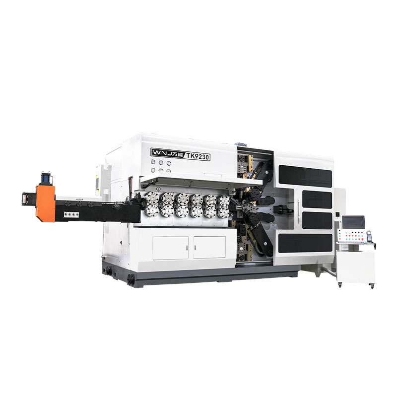
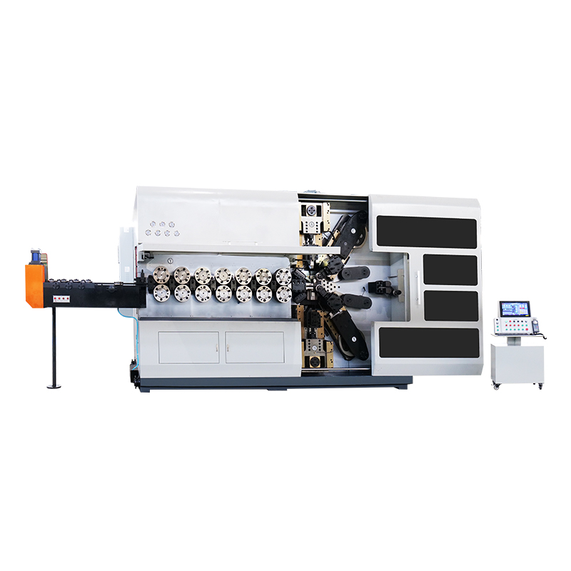
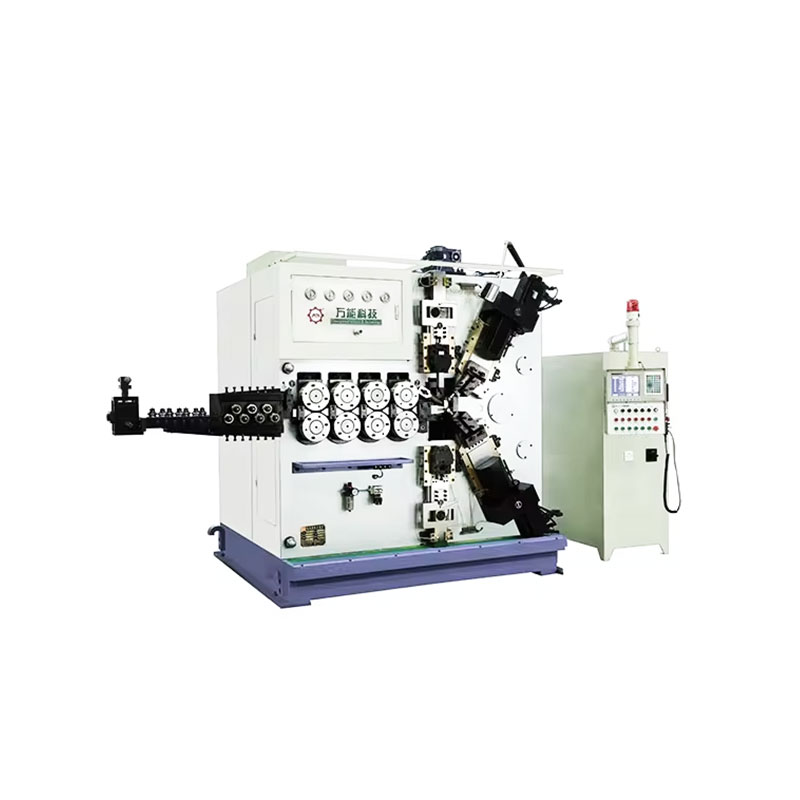
A spring bending machine — also referred to as a spring coiling machine, CNC spring former, or wire forming machine depending on configuration — is a highly specialized bending metal machine designed to process wire stock into springs and wire forms at high throughput. Understanding its operating principle helps clarify why it cannot simply be replaced by a general-purpose bending machine.
Wire is drawn from a spool or straightened from a coil and fed through precision guide rollers into the forming zone. The feed mechanism — typically a servo-driven pinch roll system — controls the length of wire dispensed to an accuracy of ±0.05 mm. In the forming zone, a coiling point or forming tool deflects the wire to create the coil diameter. The pitch tool simultaneously controls the axial advance of the coil, determining the spring's free length and pitch. A cutting mechanism — either a rotary cutter or a cam-driven cam knife — severs the finished spring from the wire at the programmed point.
On CNC spring bending machines, every axis — feed length, coiling point position, pitch tool angle, and cut timing — is independently servo-controlled and synchronized through a central motion controller. High-end machines from manufacturers such as Wafios, Itaya, or Bamatec can produce compression springs at rates exceeding 200 pieces per minute for small-diameter wire (under 1 mm), with dimensional repeatability that manual spring winding cannot approach.
Springback — the elastic recovery of metal after bending — is the central challenge in all metal bending operations, but it is especially critical in spring manufacturing. Because the spring's functional performance depends on precise geometric dimensions (free length, coil diameter, pitch), any springback that causes dimensional deviation directly translates to a spring that fails load specification. CNC spring bending machines compensate for springback algorithmically: the control software overbends the wire by a calculated amount so that after elastic recovery, the finished spring lands on the target dimension. This overbend value varies with wire material, diameter, temper condition, and bend radius, and modern machines store these values in material libraries for rapid job changeover.
Purchasing a bending metal machine — whether a press brake, spring bending machine, or tube bender — requires evaluating a set of technical parameters that determine whether the machine can actually produce your parts. Relying on a salesperson's description without verifying these figures against your part requirements is how companies end up with machines that cannot do the job.
The material being bent determines tooling selection, tonnage requirements, springback compensation, and achievable bend radius. Not all metals bend equally, and a bending metal machine optimized for mild steel may produce entirely different results — or fail outright — when attempting to bend hardened spring steel or titanium.
The default reference material for bending metal machines. Mild steel (yield strength approximately 250 MPa) is forgiving, bends cleanly, and has moderate springback. It is the material used in machine tonnage ratings and die opening recommendations. Grade S235 or A36 mild steel bends reliably to a minimum inside bend radius of 0.5× material thickness without cracking.
HSLA steel (yield strength 350–700 MPa) and AHSS grades used in automotive body structures require significantly more tonnage to bend — often 2 to 3 times the tonnage required for equivalent mild steel thickness. Springback is also proportionally higher: a 90° bend in HSLA steel may require programming the punch to 84–87° to achieve 90° after springback recovery. Die opening must also be wider to prevent cracking at the bend line.
Austenitic stainless steels (304, 316) work-harden during bending, which increases resistance as bending progresses. They require approximately 50% more tonnage than mild steel of the same thickness and exhibit pronounced springback. Tool surfaces must be kept clean to prevent stainless steel from picking up contamination, which causes corrosion in service.
Aluminum requires less tonnage than steel but is more prone to surface marking and cracking if bent across the grain direction of the sheet. Temper condition is critical: 5052-H32 bends readily to a 1× thickness radius, while 6061-T6 in the same thickness may crack unless the bend radius is increased to 3–4× thickness. Spring bending machines processing aluminum wire for the electrical or packaging industries must use polished guides and forming tools to prevent surface damage.
Spring steel — typically high-carbon steel (0.6–1.0% carbon) or alloy spring steel such as 51CrV4 — is the primary material for spring bending machines. These materials have yield strengths of 1,000–2,000 MPa and extremely high springback. A spring bending machine must be capable of applying forming forces that exceed the wire's yield strength while precisely controlling the plastic deformation that determines the spring's final geometry. Music wire (ASTM A228) is the most common spring wire grade — over 70% of precision compression springs are wound from music wire or hard-drawn wire because of their consistent tensile strength and surface quality.
| Material | Yield Strength (MPa) | Springback Level | Min. Bend Radius | Tonnage vs. Mild Steel |
|---|---|---|---|---|
| Mild Steel (A36) | 250 | Low | 0.5× t | 1× (baseline) |
| HSLA Steel | 450–700 | High | 1.5–2× t | 2–3× |
| 304 Stainless | 310 | Medium-High | 1× t | 1.5× |
| 6061-T6 Aluminum | 276 | Medium | 3–4× t | 0.5× |
| Music Wire (ASTM A228) | 1,500–2,000 | Very High | 0.5–1× d | Spring machine only |
Every bending metal machine falls into one of three control tiers: manual, hydraulic/mechanical with basic controls, or full CNC. Each tier has a distinct cost-to-capability profile, and the right choice depends on production volume, part complexity, and available operator skill.
Manual folder brakes, hand-operated box and pan brakes, and manually adjusted spring coiling machines are appropriate for prototype work, very low volume production (fewer than 50 parts per run), or situations where part variety is extremely high and setups change constantly. Their capital cost is low — a manual folder brake capable of bending 1.2 mm steel across 1 m can be purchased for $500–$3,000. The tradeoff is operator-dependent quality, slow throughput, and significant physical effort for heavier gauges. In a spring manufacturing context, manual spring winding lathes are still used for prototyping and custom single-piece orders where CNC programming time would exceed the value of the parts.
Hydraulic press brakes with a simple depth stop and manually set back-gauge represent the workhorse of small and medium fabrication shops worldwide. These machines are rugged, relatively straightforward to maintain, and capable of heavy-duty work. A 100-ton, 2.5 m hydraulic press brake with a basic 2-axis back-gauge typically costs $15,000–$40,000 depending on brand and origin. They are well-suited for medium-volume runs of simple parts — straight flanges, channels, and angles in mild steel or aluminum where one or two bends per part are required.
Full CNC control transforms a bending machine into a programmable manufacturing cell. A CNC press brake stores hundreds of part programs, each defining bend sequence, back-gauge positions, punch travel depth, crowning correction, and material parameters. Operators select a program, load the part, and the machine executes the entire bend sequence automatically. Setup time for a repeat job drops from 45–90 minutes (on a manually set machine) to under 5 minutes. For a factory running 20–30 different part numbers per day, this reduction in non-productive time is worth more annually than the price premium of the CNC system.
CNC spring bending machines deliver analogous benefits: once a spring program is written and qualified, every subsequent production run starts from a known good baseline. Parameter changes — coil diameter, free length, pitch — require only software edits rather than mechanical adjustments. Leading CNC spring machine controllers from Wafios (Germany) and Itaya (Japan) include real-time dimensional feedback: an integrated measuring system checks every spring against the programmed specification, rejecting out-of-tolerance parts automatically. First-article qualification time drops by 60–80% compared to manually set coiling machines.
The bending machine is only as capable as its tooling. For press brakes, the punch and die set determines the minimum bend radius, achievable bend angle, and maximum material thickness. For spring bending machines, the coiling tools, pitch tools, and cutting tools define the spring geometries that can be produced. Tooling is a recurring cost that must be factored into the total cost of ownership calculation.
Standard European-style (Trumpf/Wila compatible) press brake tooling has become the de facto global standard, with tooling from one manufacturer fitting machines from dozens of others. Punch profiles range from acute angle punches (30°) for tight flanges to gooseneck punches for deep box bending to hemming punches for zero-radius folds. V-die openings are selected based on material thickness: the industry rule of thumb is V-opening = 6–10× material thickness for air bending. Hardened tool steel punches and dies in standard configurations last 500,000 to 1,000,000 strokes before requiring reconditioning. Specialty tooling — roller followers for radius bending, offset punches for narrow flanges — adds versatility but increases tooling inventory cost.
Tooling for a spring bending machine is more application-specific than press brake tooling. Coiling points are typically tungsten carbide tipped to withstand the continuous abrasion of high-tensile wire at high speed. A coiling point may last 50–200 million cycles before replacement, but this varies significantly with wire surface condition and lubrication. Pitch tools, guide tubes, and cut-off tools are similarly subject to wear and must be checked at regular intervals. Maintaining a stock of tooling consumables — particularly for high-volume production springs — prevents costly unplanned downtime. The cost of a complete tooling set for a new spring profile on a CNC spring bending machine ranges from $200 to $2,000 depending on complexity, which is modest compared to the cost of press brake tooling for unusual part geometries.
Every bending metal machine operation encounters recurring quality issues. Identifying the root cause — machine, tooling, material, or programming — is the prerequisite for fixing the problem. The following are the most common defects encountered in press brake and spring bending operations, with their causes and corrections.
Symptom: A 90° bend measures 90° at the center but 92° at the ends, or vice versa. Cause on a press brake: machine frame deflection (bowing) under load, causing the center of the bed to deflect more than the ends. Correction: activate the crowning system; if the machine lacks crowning, use a segmented die with thicker sections at the center, or reduce the bend length to stay within the machine's rated straight-bend capacity. On a spring bending machine, pitch variation along the spring length suggests a worn pitch tool or inconsistent wire straightening.
Symptom: Parts bent to the same program come out with slightly different angles — within a single batch or between batches. Cause: material property variation between coils or sheets. Even certified material to the same grade can vary by ±5–10% in yield strength between production heats. Correction: bottom bending (coining) instead of air bending eliminates springback variation at the cost of higher tonnage — the material is fully plastically deformed through its thickness. For spring bending, this manifests as free length scatter and is corrected by tightening wire supplier specifications (tensile strength range), improving wire straightening, and using closed-loop feedback measurement to adjust forming parameters in real time.
Symptom: The outer surface of the bend develops micro-cracks or visible fractures. Causes: bend radius too tight for the material, bending against the material's grain direction (rolling direction), or using hardened material that has insufficient ductility. Correction: increase the inside bend radius (minimum 1× material thickness for most steels in the transverse direction, 2× in the longitudinal direction for harder alloys). For sheet metal, orient parts so the bend line is perpendicular to the rolling direction. For spring wire, cracking indicates wire surface defects or a coiling radius below the minimum for that wire diameter and temper.
Symptom: Spring free length starts at nominal and gradually increases or decreases over the course of a production run without program changes. Cause: thermal expansion of the machine's feed rollers or forming tools as the machine warms up from cold start, or progressive wear of the coiling point changing the effective coiling radius. Correction: allow a 15–20 minute warm-up period before production measurement; monitor and log free length on a statistical process control chart throughout the run; establish tool change intervals based on measured length drift rather than arbitrary time intervals.
Understanding which industries depend most heavily on bending metal machines helps contextualize the scale of this equipment category and the stakes involved in machine selection and maintenance.
A single passenger vehicle contains an estimated 100 to 200 individual spring components — valve springs, suspension springs, seat springs, brake return springs, clutch springs, and dozens of wire clips and retainers. Every one of these is produced on a spring bending machine. Sheet metal bending machines produce body reinforcements, brackets, heat shields, and structural members. The automotive industry's tolerance requirements — combined with production volumes measured in millions of units annually — make CNC bending machines with in-process measurement and statistical process control essential.
Aerospace applications demand traceability and certification at every production step. CNC bending machines in aerospace facilities must maintain complete audit trails — recording which program was used, what the machine parameters were, and what the measured dimensions of each part were. Titanium, Inconel, and aluminum-lithium alloys present extreme bending challenges: titanium's springback is approximately twice that of steel at equivalent thickness, requiring sophisticated overbend compensation. Spring bending machines in aerospace produce landing gear springs, ejector seat springs, and control cable return springs to precise load specifications verified by mandatory load testing.
The electronics industry uses spring bending machines to produce contact springs for connectors, battery contacts, switch springs, and wire form retainers in materials ranging from phosphor bronze and beryllium copper to stainless steel. These parts are often extremely small — wire diameters of 0.1–0.5 mm are common — and require production rates of several hundred pieces per minute with dimensional tolerances of ±0.02 mm. Sheet metal bending machines produce enclosures, chassis, and heat sink brackets for electronic equipment in aluminum and steel.
Press brakes and folder brakes dominate construction and HVAC metal fabrication, producing ductwork, flashing, fascia panels, structural brackets, lintel angles, and equipment enclosures from galvanized steel, aluminum, and stainless steel sheet. A sheet metal shop serving the HVAC trade may operate 3–8 press brakes of various capacities to handle different gauge materials and part sizes. Productivity in these shops is measured by linear meters of bent profile per shift — a well-run CNC press brake operation can produce 2,000 to 4,000 linear meters of bent product per 8-hour shift, depending on part complexity and material.
Medical springs and wire forms — catheter guide wires, surgical clip springs, implant fixation springs, and diagnostic equipment components — are produced on precision spring bending machines to biomedical-grade specifications. Materials in this sector include 316L stainless steel, nitinol (nickel-titanium shape memory alloy), and titanium. Nitinol wire forming on a spring bending machine is particularly challenging: the material's superelastic behavior means standard springback models do not apply, and tool paths must be developed empirically for each part geometry.
Sourcing a bending metal machine — particularly a spring bending machine — requires more due diligence than most capital equipment purchases because the machine's capability is highly application-specific and the performance differences between suppliers are significant. The following checklist applies regardless of whether you are buying new, refurbished, or used.
A supplier who can run your actual sample parts on their demonstration machine and show you the first-article inspection results is infinitely more valuable than one who provides only specification sheets. Insist on a machine demonstration with your wire or sheet material before committing to a purchase. Ask for references from customers in your industry and contact them. Ask specifically about accuracy over time (not just out-of-box performance), spare parts availability, and technical support responsiveness when the machine goes down during production.
The purchase price of a bending metal machine is typically 40–60% of its total cost of ownership over a 10-year operating life. The balance comprises tooling ($5,000–$50,000 over the life of the machine for a press brake), maintenance and spare parts (budget 2–4% of purchase price annually), energy consumption (an 80-ton hydraulic press brake consumes approximately 7.5 kW; an equivalent electric servo machine consumes 1.5–2 kW on average), and operator training. For a spring bending machine, add wire scrap cost during setup — a poorly programmed spring forming job on a CNC machine can consume 5–15 kg of wire before a good sample is achieved, which at $3–$8/kg for music wire represents $15–$120 in raw material loss per setup.
A used press brake from a reputable manufacturer — AMADA, Trumpf, Bystronic, LVD — can deliver 80–90% of new machine capability at 30–50% of the purchase price, provided the machine has been properly maintained and the CNC controller and hydraulic system are in good condition. Key inspection points include ram parallelism (check with a precision level across the ram at multiple positions), back-gauge positioning accuracy (verify with a test program running 20 consecutive positioning cycles and measuring variation), and hydraulic oil condition and system pressure stability. For used spring bending machines, inspect coiling tool wear, feed roller condition, and verify the control system can communicate with current programming software — obsolete proprietary controllers can make a machine effectively unusable if the software is no longer supported.
Press brakes and spring bending machines are among the most injury-prone machine tools in metal fabrication. The press brake in particular has a long history of hand and finger injuries caused by the fast-closing punch and die. Modern safety standards have significantly reduced injury rates, but compliance requires understanding the specific safety systems involved.
Spring bending machines present a different injury profile: the primary hazard is flying wire ends during coiling, particularly when a wire break or mis-feed occurs at high production speed. Wire ends at 150–200 m/min can cause severe lacerations. Enclosed guarding around the forming zone, mandatory PPE (safety glasses and cut-resistant gloves), and automatic stop systems triggered by wire break sensors are the minimum safety requirements. Spring bending machines should never be operated with guards removed, even during setup and adjustment — a practice that dramatically increases injury risk and is a leading cause of the injuries that do occur in spring manufacturing facilities.
TK-6160 TK-6160 CNC SPRING ROLLING MACHINE...
詳細を見る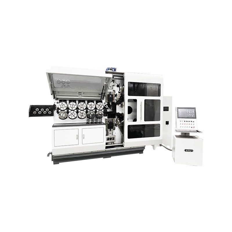
TK-6120 TK-6120 CNC SPRING ROLLING MACHINE...
詳細を見る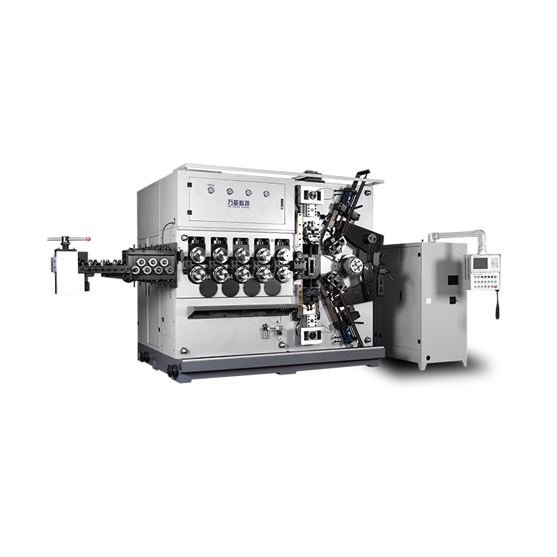
TK-5200 TK-5200 5AXES CNC SPRING COILING MACHINE...
詳細を見る
TK-5160 TK-5160 5AXES CNC SPRING COILING MACHINE...
詳細を見る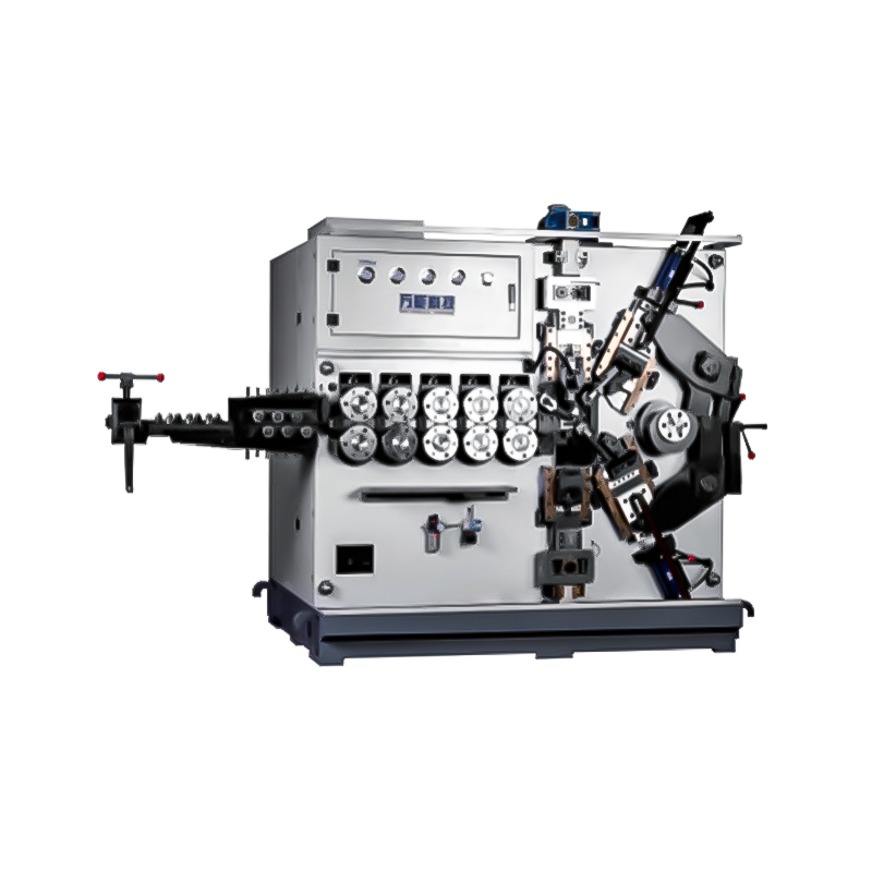
TK-5120 TK-5120 5AXES CNC SPRING COILING MACHINE...
詳細を見る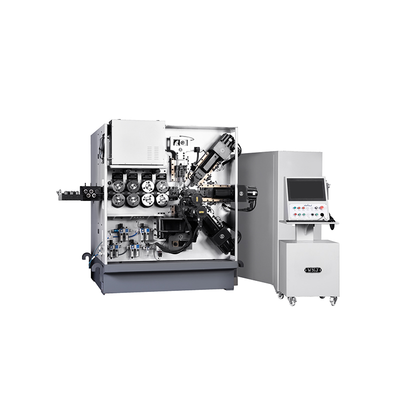
TK TK 10AXES CNC SPRING SCROLL MACHINE...
詳細を見る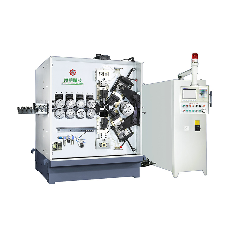
TK-580B、 TK-590 TK-580B、 TK-590 5AXES CNC SPRING COILING MACHINE...
詳細を見る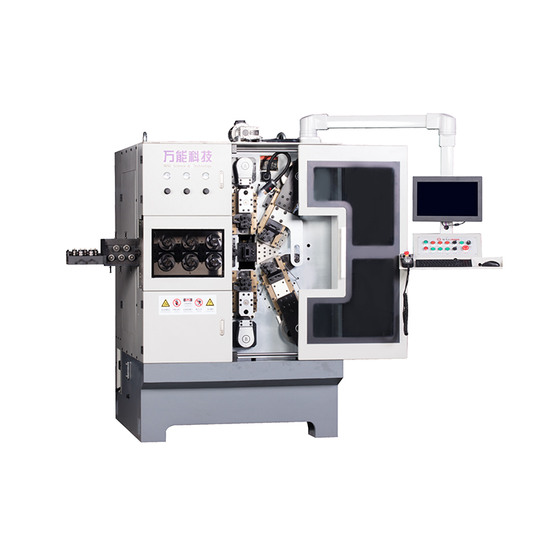
TK-760TK-760 6-7AXES CNC SPRING COILING MACHINE...
詳細を見るMobile QR Code

 Language
  中文简体
中文简体 English
 русский
 Español