Content
A temper furnace is a type of industrial heat treatment furnace specifically designed to perform the tempering process on metals — most commonly hardened steel. Its core function is to reheat a previously quenched or hardened metal component to a temperature below its lower critical point, hold it at that temperature for a controlled period, and then allow it to cool in a regulated manner. This process relieves internal stresses, reduces brittleness, and improves toughness without significantly sacrificing hardness.
To put it plainly: after steel is hardened, it becomes extremely hard but also dangerously brittle. A temper furnace is the tool that corrects this imbalance. It transforms a brittle, stress-loaded part into a component with a carefully calibrated combination of hardness and ductility — suitable for real-world mechanical loads.
Temper furnaces are widely used across the automotive, aerospace, tooling, bearing, and spring manufacturing industries. They process everything from cutting tools and gears to structural components and surgical instruments. The operating temperature range of a typical temper furnace is 150°C to 700°C (302°F to 1292°F), depending on the material and target mechanical properties.
The working principle of a temper furnace is grounded in controlled thermal metallurgy. When steel is quenched after austenitizing, it transforms into martensite — a supersaturated, body-centered tetragonal crystal structure that is extremely hard but highly stressed and brittle. Tempering, carried out inside the temper furnace, triggers a series of diffusion-controlled phase transformations within the martensite that progressively reduce stress and restore ductility.
The process follows a clear sequence of physical and metallurgical events:
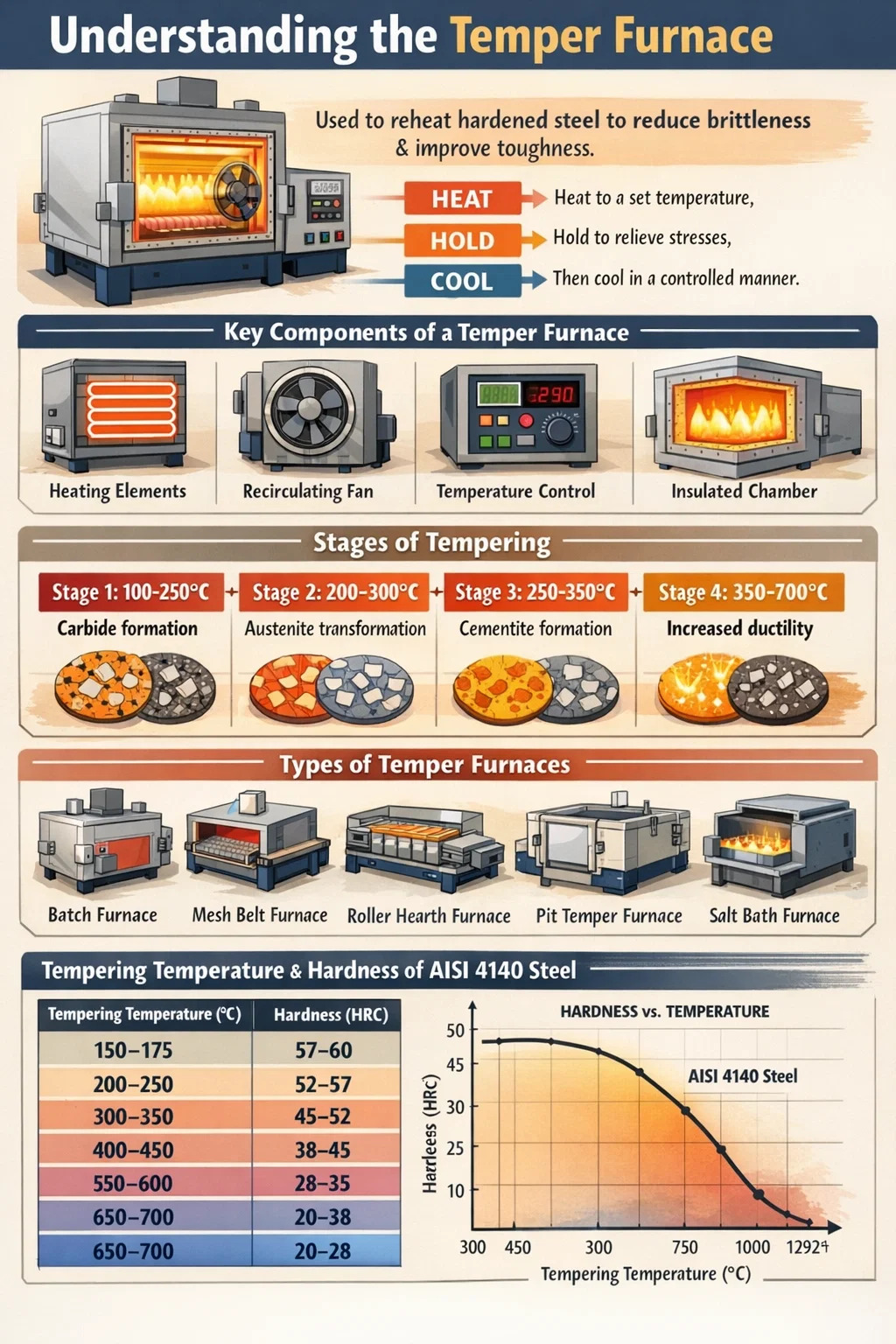
The metallurgical changes during tempering can be broken into four distinct stages based on temperature:
The temper furnace must maintain tight temperature control throughout all these stages. Modern systems achieve uniformity within ±3°C to ±5°C across the work zone, which is essential for consistent part performance.
Understanding the design of a temper furnace helps explain why it achieves consistent, repeatable metallurgical results. The major components work together to deliver uniform heat, controlled atmosphere, and reliable temperature measurement.
Temper furnaces use either electric resistance heating elements or gas-fired burners. Electric systems — often using nichrome, Kanthal, or silicon carbide elements — offer cleaner operation and more precise control. Gas-fired systems offer lower operating costs for high-volume production. The heating system is sized to meet the thermal load of the charge (typically expressed in kW or BTU/hr).
The furnace chamber is lined with refractory bricks or ceramic fiber insulation. Ceramic fiber modules are increasingly preferred because they have lower thermal mass, meaning faster heat-up times and lower energy consumption. A well-insulated chamber reduces heat loss and stabilizes temperature distribution.
Forced hot air recirculation is one of the most important features of a modern temper furnace. High-velocity fans circulate heated air across the workpieces, eliminating temperature stratification. Without recirculation, the top of a loaded furnace can be 30–50°C hotter than the bottom. A recirculating fan system brings temperature uniformity to within ±5°C or better across the entire load.
Thermocouples (typically Type K or Type N) monitor temperature at multiple points in the furnace. A PID (Proportional-Integral-Derivative) controller or a programmable logic controller (PLC) manages the heating elements based on thermocouple feedback. High-end systems incorporate data loggers that record every cycle for traceability — a requirement in aerospace (AMS 2750) and automotive heat treatment standards.
Depending on application requirements, a temper furnace may operate in air, nitrogen, or a protective endothermic atmosphere. Atmosphere control prevents surface oxidation and decarburization during tempering, particularly important for precision tool steel components and bearing rings.
Parts can be loaded manually on trays, or automatically via conveyors, roller hearths, or pusher systems. Batch tempering furnaces handle individual loads, while continuous tempering furnaces — such as roller hearth or mesh belt temper furnaces — process parts in a steady stream, suitable for high-volume operations like fastener, spring, or bearing production.
Temper furnaces come in several configurations, each suited to different production volumes, part geometries, and process requirements. Choosing the right type directly impacts energy efficiency, throughput, and temperature uniformity.
| Furnace Type | Operation Mode | Typical Temperature Range | Best Suited For |
|---|---|---|---|
| Box / Batch Temper Furnace | Batch | 150–700°C | Tooling, dies, mixed part types |
| Pit / Vertical Temper Furnace | Batch | 150–650°C | Long shafts, bars, rods |
| Mesh Belt Temper Furnace | Continuous | 150–500°C | Small parts: fasteners, bearings, springs |
| Roller Hearth Temper Furnace | Continuous | 200–700°C | Large flat parts, automotive stampings |
| Car Bottom Temper Furnace | Batch | 200–700°C | Heavy forgings, large industrial components |
| Salt Bath Temper Furnace | Batch | 150–600°C | Fast, uniform tempering of precision parts |
Among these, the mesh belt temper furnace is the most prevalent in mass production environments. A single mesh belt furnace line can process hundreds of kilograms of parts per hour, making it the backbone of bearing and fastener heat treatment operations worldwide.
The single most influential variable in the tempering process is temperature. Within the temper furnace, the selected temperature directly determines the trade-off between hardness and toughness. As tempering temperature increases, hardness decreases and toughness increases — but the relationship is not linear and depends heavily on alloy composition.
For a common medium-carbon steel like AISI 4140, here is how tempering temperature affects Rockwell hardness (HRC) after oil quenching:
| Tempering Temperature (°C) | Hardness (HRC) | Typical Application |
|---|---|---|
| 150–175 | 57–60 | Cutting tools, wear surfaces |
| 200–250 | 52–57 | Bearings, bushings |
| 300–350 | 45–52 | Springs, hand tools |
| 400–450 | 38–45 | Gears, shafts, connecting rods |
| 550–600 | 28–35 | Structural components, pressure vessels |
| 650–700 | 20–28 | High toughness forgings, heavy machinery |
One important phenomenon to be aware of is temper embrittlement — a reduction in impact toughness that occurs when certain alloy steels are tempered in the range of 250–400°C (blue brittleness range) or slowly cooled through 375–575°C. Temper furnaces used for alloy steels are often programmed to avoid these temperature ranges or to cool rapidly through them to prevent embrittlement. This is why precise furnace programming matters — not just reaching a target temperature, but managing the rate and path of temperature change.
Temper furnaces are present in virtually every sector that relies on hardened steel parts. The tempering process is not optional for most engineering components — it is a mandatory step that makes the difference between a part that performs reliably in service and one that fractures under load.
The automotive sector is among the largest consumers of tempering capacity worldwide. Gears, crankshafts, camshafts, connecting rods, axle shafts, valve springs, and transmission components all pass through temper furnaces as part of their production route. A modern passenger car contains hundreds of heat-treated steel parts, and many of them require tempering to achieve the right balance of fatigue strength and impact resistance. Continuous mesh belt or roller hearth temper furnaces running 24 hours a day are standard equipment in high-volume automotive supplier plants.
Bearing rings and rolling elements require very precise tempering, typically in the range of 150–180°C, to achieve the target hardness of 58–64 HRC while eliminating retained austenite and ensuring dimensional stability. Even a 10°C deviation from the specified tempering temperature can cause hardness to fall outside tolerance. This is why bearing manufacturers invest heavily in furnace qualification and AMS 2750 / CQI-9 compliant temper furnace systems.
High-speed steel (HSS) cutting tools are typically tempered at 540–560°C — a process called secondary hardening tempering — performed two or three times to convert retained austenite and develop secondary carbides that provide red hardness. Cold work tool steels like D2 or H13 hot work die steel are tempered at different temperature ranges to optimize their specific service properties. Box batch temper furnaces are the most common choice for tool and die shops due to their flexibility in handling varied part sizes.
Landing gear components, fasteners, structural frames, and engine parts all require tempering under strictly controlled conditions. Aerospace tempering must comply with AMS 2759 specifications, which define permissible temperature ranges, hold times, thermocouple positions, and recording requirements. Temper furnaces used in aerospace typically feature multiple thermocouples, redundant control systems, and fully automated cycle recording with digital traceability.
Valve springs, suspension springs, and industrial springs are tempered at approximately 380–450°C to optimize their elastic limit and fatigue life. Continuous mesh belt temper furnaces are ideal here since spring wire or coil springs can flow through in large quantities. Proper tempering improves fatigue strength by relaxing residual stresses introduced during coiling and shot peening processes.
These three furnace types are all used for heat treatment, but they serve fundamentally different metallurgical purposes. Confusing them leads to significant process errors and scrapped parts.
The key distinction is that a temper furnace is always used after hardening, as a corrective step. Annealing and normalizing are typically done before final hardening, as preparatory steps. The operating temperature ranges also differ significantly: tempering stays below 700°C, while annealing and normalizing often operate above 800–950°C.
Getting tempering right requires more than just setting a dial. Several interacting parameters must be managed simultaneously to achieve the desired outcome consistently.
Temperature uniformity surveys (TUS) — as required by AMS 2750 and similar standards — measure the actual temperature distribution across the furnace work zone using multiple calibrated thermocouples. Furnaces are classified into accuracy classes based on their uniformity: Class 2 (±6°C) and Class 3 (±8°C) are common for precision parts, while Class 5 (±14°C) may be acceptable for less critical applications. Inadequate temperature uniformity is one of the leading causes of rejected heat treatment lots.
Soak time is calculated based on section thickness — a common rule of thumb is 1 hour per inch (25 mm) of cross-section, with a minimum of 1 hour. Insufficient soak time leaves residual stresses in the core of thick sections. Excessive soak time at temperatures above 500°C for certain alloy steels risks temper embrittlement or grain growth. Both extremes degrade performance.
Overloading a temper furnace or stacking parts tightly impedes airflow and creates temperature gradients within the load. Parts should be arranged to allow adequate air circulation. Basket or tray fixtures are often used to maintain separation between parts. In continuous furnaces, the belt loading density (kg/m²) is a critical process parameter.
For parts where surface integrity is critical — such as precision gears or bearing races — a neutral or slightly reducing atmosphere prevents oxidation and decarburization during tempering. Nitrogen or nitrogen-methanol atmospheres are commonly used in atmosphere-controlled temper furnaces. Parts tempered in open air at high temperatures can develop surface oxide layers that must be removed by shot blasting or tumbling, adding cost and cycle time.
For most plain carbon and low-alloy steels, cooling rate after tempering has minimal impact on final properties. However, for certain alloy steels — particularly those containing Mn, Cr, Ni, or P — slow cooling through 375–575°C causes temper embrittlement, a dramatic drop in notch toughness. These steels must be water or oil quenched after tempering to bypass this range rapidly.
Energy costs represent a significant fraction of operating expenses in any heat treatment facility. Modern temper furnace designs incorporate multiple strategies to reduce energy consumption without compromising metallurgical performance.
Some advanced continuous temper furnace systems now achieve specific energy consumption below 0.15 kWh per kilogram of processed steel — a significant improvement over older designs that consumed 0.25–0.35 kWh/kg.
Even with a properly designed temper furnace, process errors can introduce defects that compromise part performance. Understanding these defects and their root causes helps operators set up and maintain their tempering process correctly.
TK-6160 TK-6160 CNC SPRING ROLLING MACHINE...
詳細を見る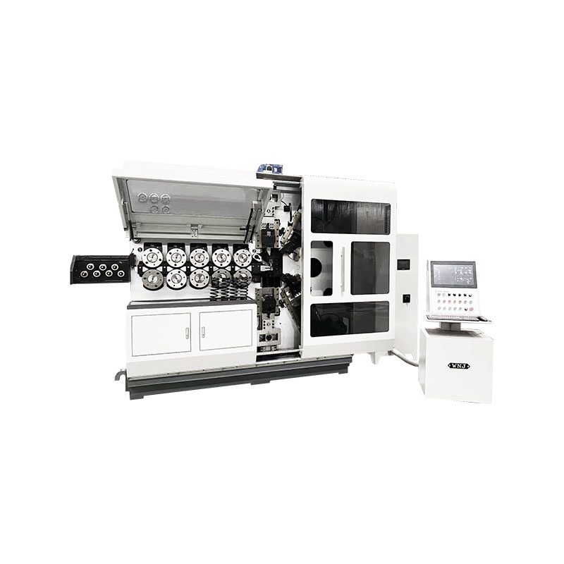
TK-6120 TK-6120 CNC SPRING ROLLING MACHINE...
詳細を見る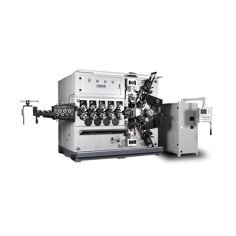
TK-5200 TK-5200 5AXES CNC SPRING COILING MACHINE...
詳細を見る
TK-5160 TK-5160 5AXES CNC SPRING COILING MACHINE...
詳細を見る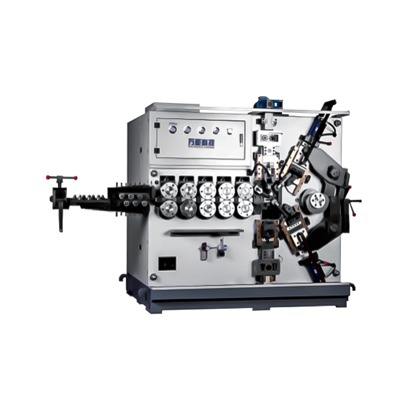
TK-5120 TK-5120 5AXES CNC SPRING COILING MACHINE...
詳細を見る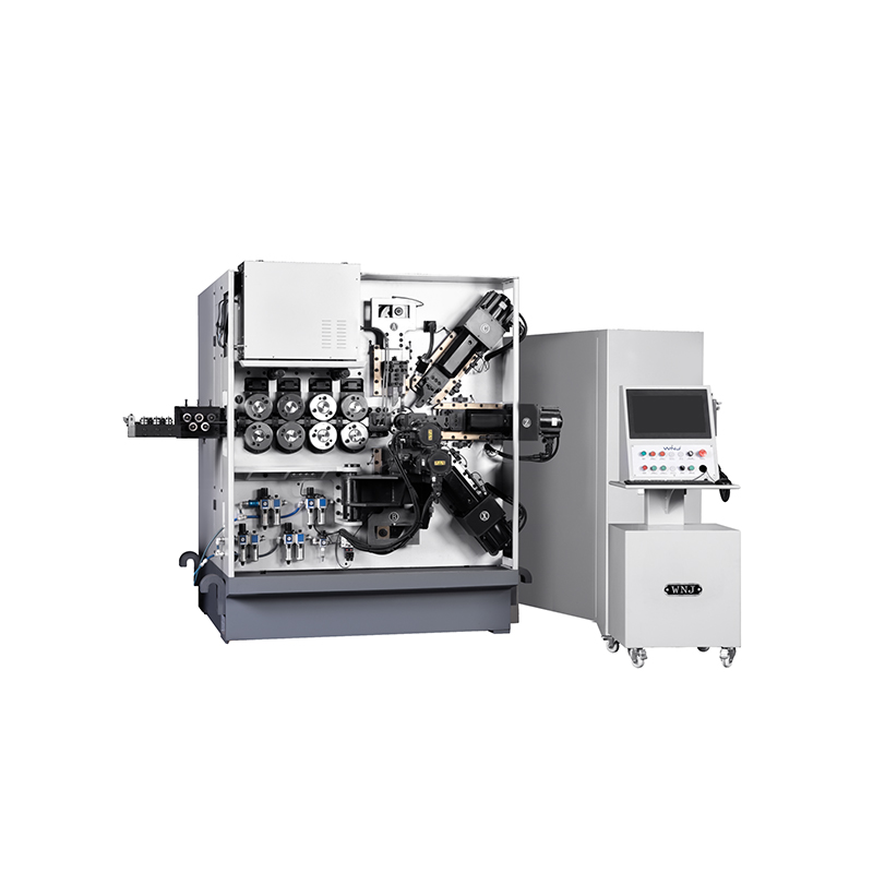
TK TK 10AXES CNC SPRING SCROLL MACHINE...
詳細を見る
TK-580B、 TK-590 TK-580B、 TK-590 5AXES CNC SPRING COILING MACHINE...
詳細を見る
TK-760TK-760 6-7AXES CNC SPRING COILING MACHINE...
詳細を見るMobile QR Code

 Language
  中文简体
中文简体 English
 русский
 Español