Content
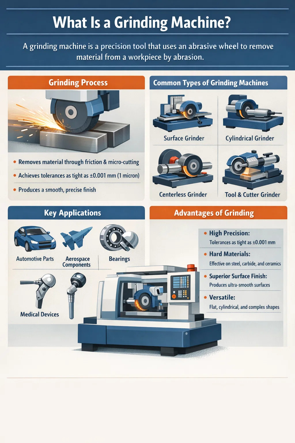
A grinding machine is a precision power tool or industrial machine that uses an abrasive wheel — or other abrasive cutting tool — to remove material from a workpiece by abrasion. The result is a finely finished surface, a precise dimension, or a sharpened edge. In manufacturing, grinding machines are classified as a subtype of machine tools, and they serve a critical role in finishing operations where tolerances as tight as ±0.001 mm (1 micron) are required.
Unlike turning or milling, which use defined-geometry cutting tools, grinding relies on abrasive grains — irregular particles of hard material such as aluminum oxide, silicon carbide, cubic boron nitride (CBN), or diamond — bonded together into a wheel. Each grain acts as a tiny, undefined cutting edge. This makes grinding ideal for hard materials and super-precise finishing work that softer or larger cutting tools simply cannot achieve.
Grinding machines are found in virtually every metal fabrication and manufacturing environment, from automotive component production to aerospace engineering, tool and die making, bearing manufacturing, and medical device fabrication. The global grinding machine market was valued at approximately USD 5.1 billion in 2023 and continues to grow, driven by demand for precision parts in high-tech industries.
The working principle of a grinding machine is based on abrasive machining — the mechanical removal of material through friction and micro-cutting by abrasive particles. Understanding how this process works in detail helps operators optimize grinding performance and achieve consistent results.
When the grinding wheel rotates at high speed — typically between 1,500 and 3,000 RPM for bench grinders, or up to 60 m/s surface speed for high-speed production grinding — each abrasive grain on the wheel's surface makes brief contact with the workpiece. During this contact, the grain either cuts a tiny chip, plows the material (causing plastic deformation), or slides over the surface (causing friction and heat).
The ratio of cutting, plowing, and sliding depends on multiple factors: grit size, wheel hardness, workpiece material hardness, depth of cut, and the presence of cutting fluid (coolant). A well-tuned grinding setup maximizes cutting and minimizes plowing and sliding, which improves surface finish and reduces heat buildup.
The grinding wheel and the workpiece move relative to each other in a controlled manner. The wheel rotates at high peripheral speed, while the workpiece is held in a fixture (a chuck, between centers, or on a magnetic table) and fed into the wheel at a controlled rate. This feed rate, combined with the depth of cut, determines the material removal rate (MRR) and the resulting surface quality.
In surface grinding, for example, the workpiece (usually a flat metal part) is moved back and forth beneath the rotating wheel on a reciprocating table, with the wheel lowered incrementally — often by just 0.005 to 0.025 mm per pass — until the desired dimension is achieved. In cylindrical grinding, the workpiece rotates on its own axis while the wheel simultaneously rotates and traverses along the workpiece length.
One of the most important and unique aspects of grinding wheel behavior is self-sharpening. As abrasive grains become dull during use, the grinding forces acting on them increase. Eventually, either the grain fractures (exposing a new sharp edge) or the bond holding the grain breaks, releasing the dull grain and exposing a fresh sharp one underneath. This is why the "grade" (hardness) of a grinding wheel matters: a wheel that is too hard will retain dull grains too long (causing glazing and heat buildup), while a wheel that is too soft will shed grains prematurely (causing rapid wheel wear).
The correct wheel grade must be matched to the workpiece material. Hard materials like hardened tool steel require a softer grade wheel (so grains break away more readily), while soft materials like aluminum may need a harder grade wheel to prevent the wheel from wearing too fast.
Grinding generates significant heat due to friction. Temperatures at the grinding zone can momentarily reach 800°C to 1,500°C in extreme cases. Without proper cooling, this heat causes thermal damage to the workpiece: burning, microcracking, residual stress, surface hardness changes, and dimensional inaccuracies. Cutting fluids (coolants) — usually water-based emulsions or synthetic fluids — are applied at the grinding zone to absorb heat, lubricate the contact area, and flush away swarf (fine metal and abrasive particles). Proper coolant application is as important to grinding quality as wheel selection or feed rate.
There is no single universal grinding machine. Different types are designed and optimized for specific workpiece geometries, materials, and precision requirements. Here is a detailed breakdown of the most common types:
Surface grinding machines produce flat surfaces on workpieces. The most common configuration uses a horizontal spindle with a peripheral grinding wheel and a reciprocating worktable. The workpiece is typically held on a magnetic chuck. Surface grinders are widely used to finish tool steel plates, mold bases, machine slides, and any part requiring a flat, smooth reference surface. Flatness tolerances of 0.002 to 0.005 mm are routinely achievable.
Cylindrical grinders are used to grind the external or internal surfaces of cylindrical workpieces such as shafts, pins, sleeves, and bores. In external cylindrical grinding, the workpiece rotates between centers or in a chuck, and the wheel traverses along its length. Internal cylindrical grinding (ID grinding) uses a small wheel inserted into a bore to grind the inner surface. Cylindrical grinding is essential for producing bearing seats, hydraulic cylinder rods, and precision spindles — components that require roundness tolerances of 0.001 mm or less.
In centerless grinding, the workpiece is not held between centers or in a chuck. Instead, it is supported on a work rest blade and controlled by a regulating wheel, while the grinding wheel removes material. This setup allows continuous, automated grinding of cylindrical parts like bars, tubes, and pins at very high production rates. Centerless grinders are heavily used in the production of fasteners, hydraulic components, and automotive parts. A single centerless grinder can process hundreds of parts per hour with consistent diameter tolerances.
These specialized machines grind cutting tools such as end mills, drill bits, reamers, taps, and milling cutters. They feature complex multi-axis setups and are found in tool rooms and grinding shops. The ability to re-sharpen cutting tools extends their service life significantly — a properly resharpened end mill can match the performance of a new one at a fraction of the cost.
The bench grinder is a simple, compact machine mounted on a workbench, with one or two grinding wheels mounted on a horizontal spindle. It is used for rough grinding, deburring, sharpening hand tools, and light material removal. While not a precision machine, it is one of the most common grinding machines found in workshops, garages, and maintenance facilities worldwide. Standard bench grinders typically run at 3,450 RPM and use wheel diameters of 6 to 8 inches.
The angle grinder is a handheld power tool used for cutting, grinding, and polishing metal, stone, and other materials. It is one of the most versatile and widely used power tools in construction, fabrication, and metalworking. Angle grinders use disc-type abrasive wheels, cutting discs, flap discs, or wire brushes, and typically operate at speeds between 6,000 and 12,000 RPM. Common disc diameters are 4.5 inches (115 mm), 5 inches (125 mm), and 9 inches (230 mm).
| Type | Primary Use | Typical Tolerance | Key Industry |
|---|---|---|---|
| Surface Grinder | Flat surfaces | ±0.002–0.005 mm | Tooling, Mold Making |
| Cylindrical Grinder | Shafts, bores | ±0.001 mm | Automotive, Aerospace |
| Centerless Grinder | High-volume cylinders | ±0.002 mm | Fasteners, Hydraulics |
| Tool & Cutter Grinder | Resharpening tools | ±0.005 mm | Tool Rooms |
| Bench Grinder | Deburring, sharpening | Not precision | Maintenance, Workshop |
| Angle Grinder | Cutting, grinding, polishing | Not precision | Construction, Fabrication |
Understanding the main components of a grinding machine helps demystify how the machine achieves precision and control. While configurations vary by machine type, most grinding machines share the following core components:
The grinding wheel is the heart of any grinding machine. Selecting the wrong wheel is one of the most common causes of poor results — burning, chatter, rapid wheel wear, or poor surface finish. Grinding wheels are specified by a standardized system that encodes five key characteristics:
As a practical example, a wheel marked A46-L5-V is an aluminum oxide wheel, 46 grit (medium), L grade (medium-hard), structure 5 (medium dense), vitrified bond — a typical general-purpose wheel for surface grinding steel.
Understanding the sequence of a grinding operation — not just the machine itself — is essential for achieving consistent, high-quality results. Here is a typical sequence for precision surface grinding:
One of the primary reasons for choosing grinding over other machining processes is the exceptional surface finish it can produce. Surface finish is measured by parameters such as Ra (arithmetic mean roughness), Rz (mean roughness depth), and Rmax (maximum roughness height). Here is what grinding can realistically achieve:
For reference, a standard turned shaft surface has Ra 1.6–3.2 µm. A bearing race ground to Ra 0.2 µm is far smoother — this level of finish is critical for rolling element bearings, precision spindles, and hydraulic sealing surfaces. The finer the grit and the lighter the finishing pass, the lower the Ra value that can be achieved.
The shift from manual to CNC (Computer Numerical Control) grinding machines has transformed precision manufacturing over the past three decades. A modern CNC cylindrical grinder, for example, can operate with 5 to 7 simultaneous CNC axes, automatically dress the wheel, perform in-process gauging (measuring the workpiece dimension while grinding), and compensate for wheel wear in real time — all without operator intervention.
Key advantages of CNC grinding machines over manual machines include:
Major manufacturers of CNC grinding machines include STUDER (Switzerland), JUNKER (Germany), Okuma (Japan), ANCA (Australia), and United Grinding Group. High-end CNC cylindrical grinders from these manufacturers can cost anywhere from USD 150,000 to over USD 1,000,000 depending on size, capability, and automation level.
Grinding machines are powerful and involve rapidly spinning abrasive wheels that, if misused, can cause serious injury. The U.S. Occupational Safety and Health Administration (OSHA) standard 29 CFR 1910.215 specifically governs abrasive wheel machinery safety. Key safety practices include:
Grinding is not always the right choice. Knowing when to grind and when to use other processes is part of good manufacturing process planning.
| Process | Best For | Typical Tolerance | Typical Ra | Material Removal Rate |
|---|---|---|---|---|
| Turning | Cylindrical, rough-to-semi-finish | ±0.02–0.05 mm | 0.8–3.2 µm | High |
| Milling | Flat/contour, rough-to-semi-finish | ±0.01–0.05 mm | 0.8–3.2 µm | High |
| Grinding | Hard materials, precision finish | ±0.001–0.005 mm | 0.1–0.8 µm | Low–Medium |
| Honing | Bore geometry correction | ±0.001 mm | 0.1–0.4 µm | Very Low |
| Lapping | Ultra-fine finish, flatness | ±0.0005 mm | 0.01–0.1 µm | Extremely Low |
Choose grinding when the workpiece is hardened (HRC 50+), when surface finish requirements are Ra 0.8 µm or better, when dimensional tolerances are tighter than ±0.01 mm, or when the material (carbide, ceramic) cannot be machined by conventional cutting tools. For soft materials with relaxed tolerances, turning or milling is more cost-effective.
Grinding machines are deeply embedded in the manufacturing of precision components across virtually every high-tech industry. Here is a look at where grinding matters most:
TK-6160 TK-6160 CNC SPRING ROLLING MACHINE...
詳細を見る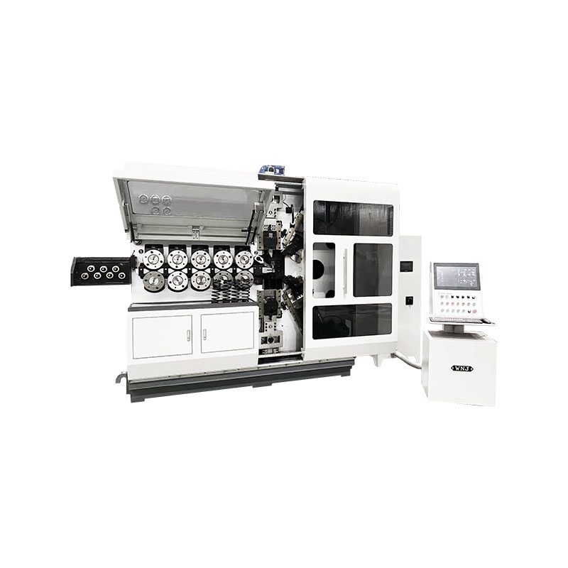
TK-6120 TK-6120 CNC SPRING ROLLING MACHINE...
詳細を見る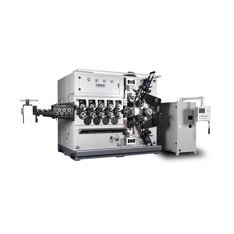
TK-5200 TK-5200 5AXES CNC SPRING COILING MACHINE...
詳細を見る
TK-5160 TK-5160 5AXES CNC SPRING COILING MACHINE...
詳細を見る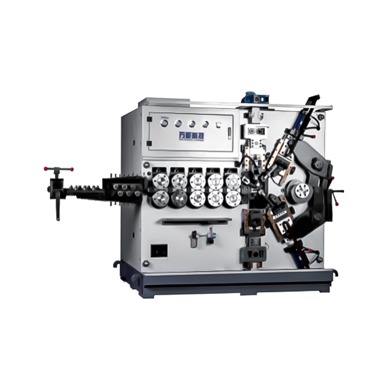
TK-5120 TK-5120 5AXES CNC SPRING COILING MACHINE...
詳細を見る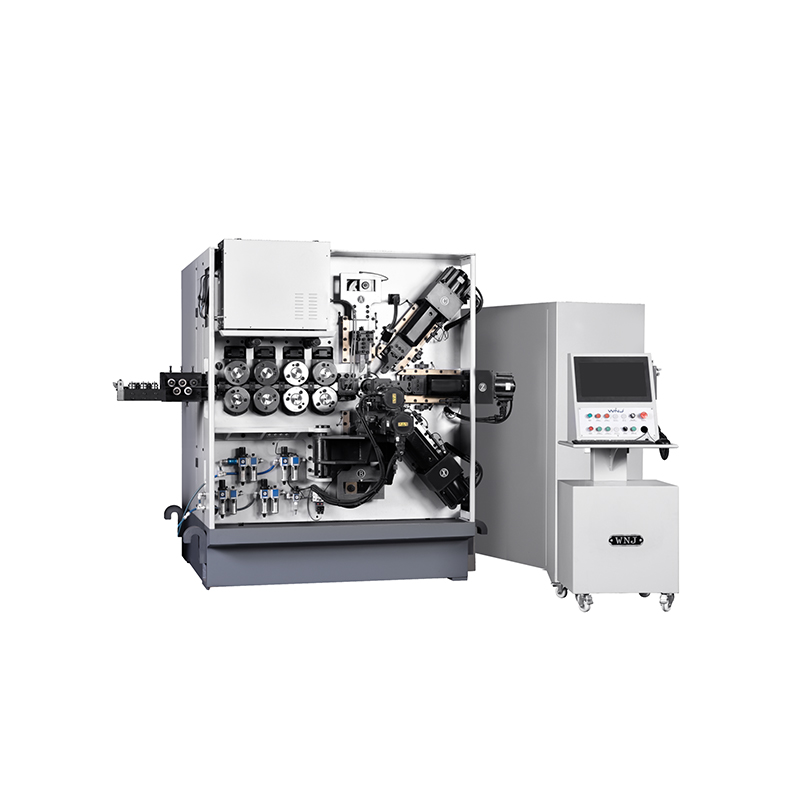
TK TK 10AXES CNC SPRING SCROLL MACHINE...
詳細を見る
TK-580B、 TK-590 TK-580B、 TK-590 5AXES CNC SPRING COILING MACHINE...
詳細を見る
TK-760TK-760 6-7AXES CNC SPRING COILING MACHINE...
詳細を見るMobile QR Code

 Language
  中文简体
中文简体 English
 русский
 Español