Language
Content
There are six primary spring types used across industrial and consumer products: compression springs, extension springs, torsion springs, constant force springs, wave springs, and disc (Belleville) springs. Each is defined by how it stores and releases mechanical energy — compressed, stretched, twisted, rotated, flattened, or stacked. The right choice depends on the load direction, available space, and how many work cycles the part must survive, and nearly all of them are formed today on a computer-controlled spring machine rather than by hand.
The category a spring falls into is really a shorthand for a mechanical behavior. A compression spring pushes back. An extension spring pulls back. A torsion spring resists a twist. Once that behavior is fixed, everything else — wire diameter, coil count, end geometry, and material — is a tuning exercise to hit a target load, deflection, and service life.
This guide breaks down each type of spring in depth, the materials behind them, how a modern spring machine shapes each one, how engineers size a spring for a real load case, where each type shows up across different industries, common failure points, finishing and corrosion protection, and how to compare quotes when sourcing production quantities.
Compression springs are open-coil springs designed to resist a squeezing force and push back when compressed. They are the most common spring type in mechanical assemblies, appearing in mattresses, ballpoint pens, valves, suspension systems, and industrial dies. When a load pushes the coils together, the spring stores energy and pushes back along the same axis once the load is released.
Because the coils sit apart from each other at rest, a compression spring can be compressed until the coils touch — a state called solid height. Good design keeps a spring well away from solid height in normal operation, since bottoming out repeatedly work-hardens the wire at the point of contact and shortens fatigue life. Most engineering guidance keeps working deflection at roughly 80 percent or less of the total available travel to solid height, leaving a safety margin for overtravel events.
Compression springs are also defined by how the end coils are finished. Plain ends leave the wire cut at an angle matching the helix, which is fast to produce but lets the spring rock slightly under load. Squared ends are ground or pressed flat so the spring stands upright on a flat surface without tipping, and squared-and-ground ends take that a step further by grinding the end coil perfectly flat, which is common wherever the spring needs to seat evenly against a flat plate, such as in valve assemblies.
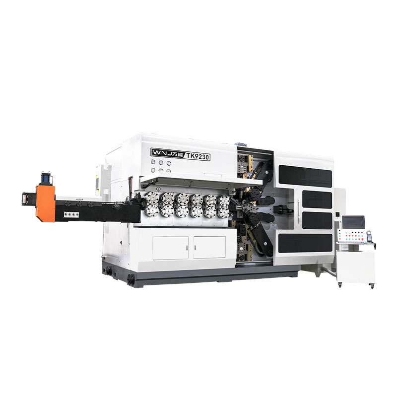
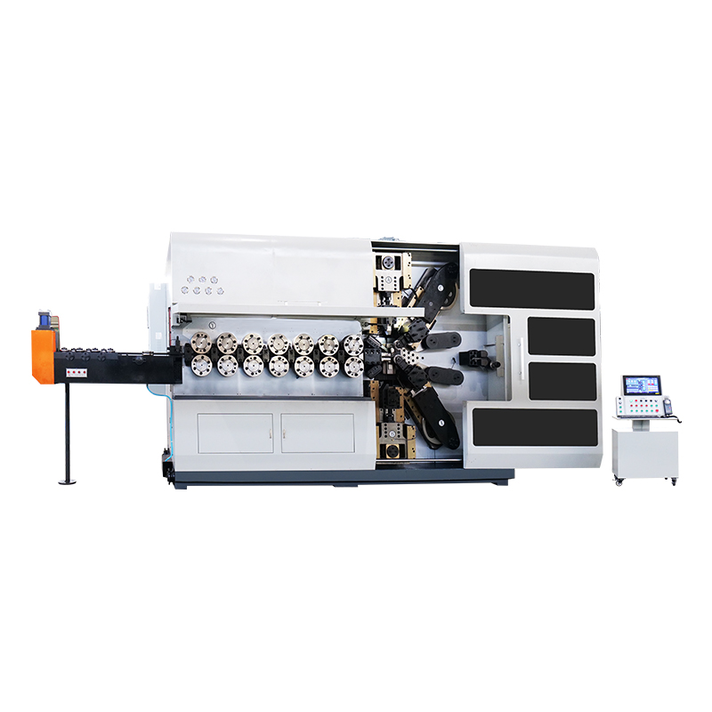
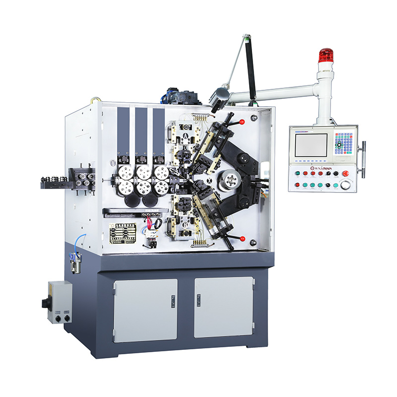
A production-grade spring machine forms compression springs by feeding wire through a set of feed rollers and wrapping it around a mandrel or forming pin, then a cutoff tool separates each coil at a programmed length. CNC-controlled machines can hold pitch tolerances tight enough to keep spring rate variation under roughly 3 percent across a production run, which matters for parts where consistent force is critical, such as valve springs. High-volume compression spring lines typically pair the coiling head with an inline grinding station so squared ends can be finished without a separate secondary operation.
Extension springs are tightly wound coils that resist a pulling force and try to return to their original length once released. Unlike compression springs, their coils sit close together at rest — usually with initial tension built in — so the spring only begins to stretch once the applied force exceeds that preload. Garage door mechanisms, trampolines, screen doors, and toggle switches all rely on extension springs.
Initial tension is one of the more misunderstood properties of an extension spring. Because the coils are wound tightly against each other during forming, the spring resists any pull at all until the applied force exceeds that built-in tension — only then does it begin to stretch in proportion to the added load. Designers specify this initial tension deliberately, since too little allows the spring to sag at rest, while too much makes the mechanism feel stiff at the start of its travel.
Most of the design work in an extension spring happens at the ends, not the coil body. Machine hooks, cross-over loops, side loops, and extended eyes each change how the spring mounts and how stress concentrates at the bend. Because the hook bend is typically where fatigue failure starts, hook geometry is often the limiting factor in a spring's working life rather than the coil itself.
On a modern spring machine, hook forming is done in the same cycle as coiling: after the coiling tool winds the body, a secondary tool rotates and bends the wire end into the hook shape before cutoff. This keeps hook alignment consistent, which is one of the more common quality complaints when extension springs are formed by hand. Consistent hook angle also matters for how the spring hangs in its mounting bracket — a twisted hook can introduce an unwanted side load the coil body was never designed to carry.
Torsion springs store energy when twisted around their axis rather than being pushed or pulled along it. The coil body resists angular displacement, and the straight legs at each end transmit that rotational force into the assembly. Clothespins, mousetraps, garage door counterbalance systems, and hinges on cabinet doors are typical examples.
Unlike compression and extension springs, a torsion spring is almost always designed to work with its coil diameter reducing slightly as it winds up under load. That means the shaft or mandrel it sits on has to be sized with clearance for this reduction, or the coils will bind against the shaft before the spring reaches its intended travel — a detail that catches many first-time designers off guard.
| Torsion Spring Feature | Design Effect |
|---|---|
| Coil direction (left or right hand) | Must match the direction the spring is intended to wind up under load, or the coils will unwind instead of tightening |
| Leg configuration | Straight, hinged, or angled legs determine how torque transfers into the surrounding assembly |
| Number of active coils | More coils generally lower the torque rate and increase the rotational travel available |
| Body style (close-wound vs. spaced) | Close-wound coils reduce friction noise between coils; spaced coils reduce the chance of binding under heavy load |
Beyond the household examples, torsion springs show up in counterbalance mechanisms for heavy overhead doors, return springs in ratchet and pawl assemblies, hinge closers on cabinets and enclosures, and clamping mechanisms where a light, consistent rotational force is needed to hold two parts together without a separate fastener.
Torsion springs are usually formed on a CNC spring machine equipped with a rotating leg-bending head, since leg angle accuracy directly affects how the spring seats in its mounting holes. A leg that is off by even a few degrees can create preload inconsistency across an assembly line, which is why leg angle is one of the first dimensions checked during incoming inspection on a new tooling setup.
Belleville springs are cone-shaped washers that flatten under axial load. Stacking them in series increases travel, while stacking them in parallel increases load capacity, which makes them useful anywhere a designer needs a specific force curve in a very short axial space — bolted flange assemblies and heavy machinery are common examples. A useful property of disc springs is that their force curve can be tuned by their cone height relative to their thickness: a shallow cone gives a nearly linear force response, while a taller cone can be tuned to produce a flat or even a snap-through force curve, which is useful in overload-release mechanisms.
Wave springs use a wavy, ring-shaped form instead of a round-wire coil, delivering the same spring force as a coil spring in roughly a third to half the compressed height. Bearing preload and small electronic connector applications favor wave springs when axial space is limited. They are typically produced in single-turn, multi-turn, and nested varieties, with multi-turn wave springs commonly used where a taller working height is available but radial space is still tight.
Rolled from pre-stressed flat strip rather than round wire, a constant force spring delivers nearly the same output force through its entire extension range instead of a rising force curve. Retractable tape measures, counterbalance mechanisms, and cable reels rely on this behavior. Because the strip is coiled onto itself in a tight roll at rest and unwinds under load, the force output stays remarkably flat compared to a coil spring's steadily rising resistance.
Gas springs are a different category altogether — a sealed cylinder with compressed gas and a piston rod, used where a controlled, dampened extension is needed, such as automotive hatch struts and adjustable office chairs. They are manufactured on hydraulic filling equipment rather than a wire-forming spring machine.
Two less common but still relevant types round out the specialty category. Volute springs are flat strip wound into a cone shape and function like a compression spring with excellent resistance to buckling, historically used in heavy vehicle suspensions. Serpentine springs are formed from a continuous zig-zag of round wire and were once common in upholstered seating, valued for spreading load evenly across a wide seat pan rather than concentrating it at a few points.
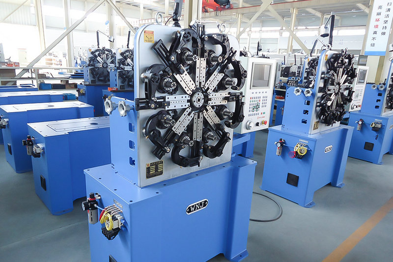
The type of spring being produced usually dictates which wire alloy makes sense, and every alloy behaves differently once it is fed through a spring machine.
Two dimensions dominate a spring's behavior more than any other single variable: wire diameter and spring index, the ratio of coil diameter to wire diameter. A thicker wire raises stiffness sharply, since spring rate scales with the fourth power of wire diameter, while a low spring index (a tight coil relative to the wire) increases stress concentration on the inside of each coil and makes the spring harder to form accurately. Most practical designs keep the spring index between roughly 4 and 12; springs coiled tighter than that need extra care in tooling and stress correction, while springs coiled looser than that tend to tangle and buckle more easily.
A CNC spring machine changes its coiling speed, wire feed rate, and forming pin pressure depending on the alloy loaded, since harder wire needs more forming force but springs back further after the tool releases it, a behavior called elastic recovery. Machines built for high-volume production typically compensate for this recovery automatically by over-forming each coil by a calculated margin, which is one reason automated coiling has largely replaced manual bench forming for anything beyond prototype quantities. Modern servo-driven spring machines log this compensation data per batch, which makes it far easier to reproduce the exact coil geometry the next time the same wire lot is run.
Choosing a spring type is only the first step. Sizing one for an actual application usually comes down to three linked targets: the spring rate (how much force changes per unit of deflection), the maximum safe stress at full deflection, and the number of cycles the spring needs to survive before fatigue becomes a concern.
Spring rate describes how stiff the spring feels — the additional force needed for each additional unit of deflection. For a coil spring, rate rises with wire diameter and falls as coil diameter or the number of active coils increases. Two springs can look nearly identical and still have very different rates if one has a slightly larger coil diameter or two more active coils than the other, which is why spring rate, not just physical dimensions, is the number that should be specified and checked.
Springs that cycle occasionally, such as a latch spring opened a few times a day, can be designed with a generous stress margin and will likely outlast the product around them. Springs that cycle continuously, such as a valve spring firing thousands of times per minute, need to be designed against a fatigue curve rather than a single peak stress value, since repeated loading well below the material's ultimate strength can still eventually cause a crack to initiate and grow. As a rough guide, keeping peak operating stress under roughly 45 to 50 percent of the wire's tensile strength is a common starting point for springs expected to survive millions of cycles, though the right number always depends on the specific alloy and surface finish.
Shot peening is the most widely used treatment for extending fatigue life in compression and torsion springs. Firing small round media at the wire surface introduces a shallow layer of compressive residual stress, which resists the tensile stress that would otherwise initiate a fatigue crack at the surface. For springs subject to high-cycle, high-stress service — automotive valve springs are the classic example — shot peening can meaningfully extend service life compared to an unpeened spring of the same dimensions.
A modern CNC spring machine turns a spool of raw wire into a finished, heat-treated spring in a sequence of coordinated steps, all controlled through programmed servo motion rather than mechanical cams on older equipment.
Older cam-driven coiling machines rely on physical cams and mechanical stops to control pitch and length, which means changing a spring design requires swapping physical tooling. A CNC spring machine replaces most of those mechanical cams with independently programmed servo axes, so switching between spring designs — including entirely different types, such as moving from a compression spring run to a torsion spring run — is largely a matter of loading a new program and adjusting tooling rather than rebuilding the machine. This flexibility is one of the main reasons small and mid-volume spring runs have become far more cost effective over the past two decades.
| Industry | Typical Spring Types | Why That Type |
|---|---|---|
| Automotive | Compression, torsion, disc | High-cycle valve and clutch applications need shot-peened compression springs; disc springs handle high load in short axial space |
| Furniture and appliances | Compression, extension, constant force | Recliner mechanisms and drawer slides need consistent, moderate-cycle force with a flat or gently rising rate |
| Electronics and connectors | Wave, small compression | Limited internal clearance favors low-profile wave springs for contact preload |
| Agriculture and heavy equipment | Compression, torsion | Large-diameter, heavy-gauge springs need to survive shock loading outdoors, favoring corrosion-resistant coatings |
| Medical devices | Compression, extension, torsion (miniature) | Stainless wire is preferred for cleanability, with tight tolerances on very small wire diameters |
A spring's material choice handles most corrosion resistance, but coatings and finishes add another layer of protection and can change the spring's appearance and friction characteristics as well.
Coating thickness matters more than it might seem for close-tolerance springs, since even a thin plating layer changes the effective wire diameter slightly and can shift spring rate on very small springs. For springs with tight rate tolerances, testing is usually done after coating rather than before, so the reported values reflect the part as it will actually be installed.
Uneven coil spacing usually traces back to wire that was not fully straightened before coiling, worn feed rollers slipping on the wire surface, or a pitch tool that has drifted out of calibration. On a CNC spring machine, this is often caught early through inline pitch measurement built into the coiling station itself.
Most fatigue cracks start at a surface defect — a scratch, a pit from corrosion, or a stress concentration at a bend or hook — rather than in the middle of a smooth coil. Improving surface finish, adding shot peening, or redesigning a sharp hook radius are the usual fixes once a fatigue failure pattern is identified.
Permanent set describes a spring that no longer returns to its original free length after being deflected, usually because it was stressed beyond the material's elastic limit — often from being compressed to solid height repeatedly, or from operating at a higher temperature than the wire alloy was rated for. Proper stress relieving after coiling reduces the risk of set by relaxing residual forming stresses before the spring ever sees its first working cycle.
A handful of variables tend to drive most of the cost difference between spring quotes, independent of which type is being produced.
When comparing quotes across suppliers, it helps to ask specifically how load and rate are being verified — most reputable producers test a sample from every production lot on a force-displacement tester rather than relying on dimensional checks alone, since two springs can measure identically and still perform differently if wire hardness varies slightly between wire lots.
The fastest way to narrow down a spring type is to ask which direction the force is applied and how much axial space is available:
Compression springs are the most widely produced type, since a straightforward push-back force covers the largest share of mechanical and consumer applications, from pens to mattress cores.
A compression spring resists being squeezed and its coils sit apart at rest, while an extension spring resists being stretched and its coils sit tight together at rest, usually with hooked or looped ends for mounting.
Yes. Most modern CNC spring machines are reprogrammed rather than mechanically rebuilt to switch between compression, extension, and torsion forming, since the difference comes down to tooling changes and updated coiling, pitch, and bending parameters in the control software.
Bends concentrate stress far more than a smoothly wound coil, so hooks on extension springs and legs on torsion springs are typically the first failure point under repeated cycling, which is why hook and leg geometry gets as much design attention as the coil itself.
In most retrofit cases, yes — a wave spring can deliver a comparable force to a coil compression spring while taking up roughly a third to half the compressed height, which is why they are common in space-limited bearing and connector designs.
Spring index is the ratio of coil diameter to wire diameter. A low index means a tightly coiled spring with higher stress concentration on the coil's inside edge, while a high index means a loosely coiled spring that is easier to form but more prone to buckling and tangling — most practical designs stay in a middle range for a balance of manufacturability and performance.
Yes, for springs that see high-stress, high-cycle loading. The compressive residual stress introduced at the wire surface resists the tensile stress that initiates fatigue cracks, which is why shot peening is standard practice for demanding applications like automotive valve springs, even though it adds a secondary process step.
Wire hardness and diameter can vary slightly between mill lots even within an accepted tolerance range, which is why consistent producers test a sample from every batch on a force-displacement tester rather than assuming dimensional conformance alone guarantees consistent load and rate.
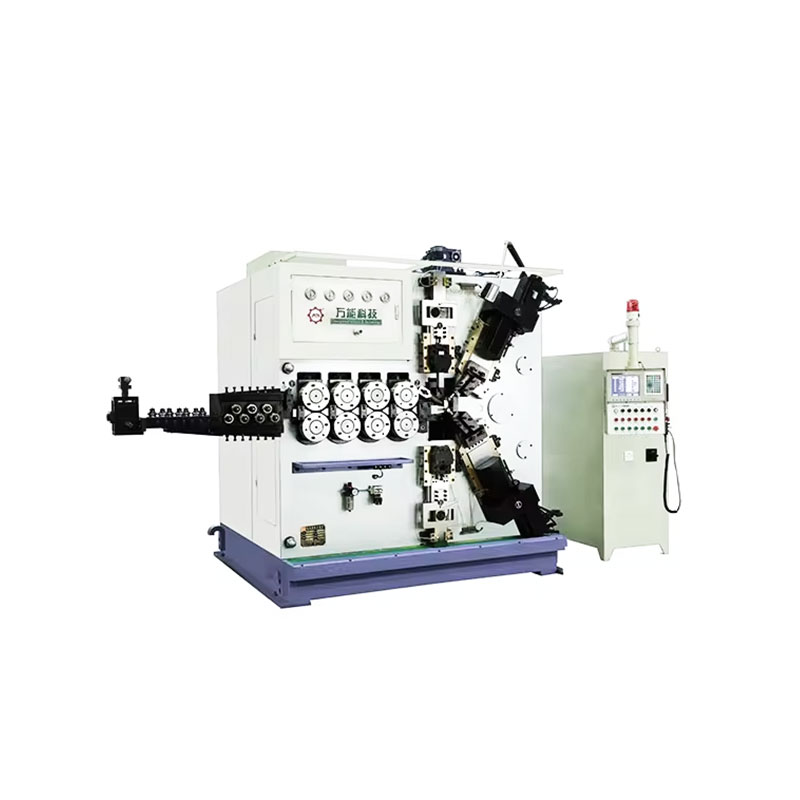
TK-6160 TK-6160 CNC SPRING ROLLING MACHINE...
See Details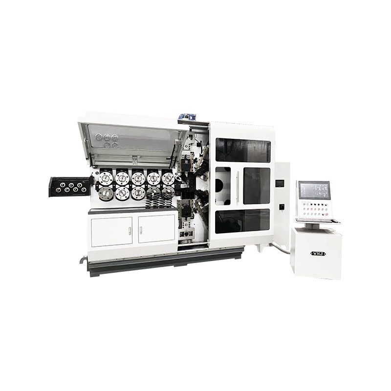
TK-6120 TK-6120 CNC SPRING ROLLING MACHINE...
See Details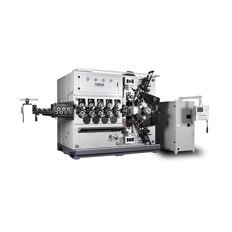
TK-5200 TK-5200 5AXES CNC SPRING COILING MACHINE...
See Details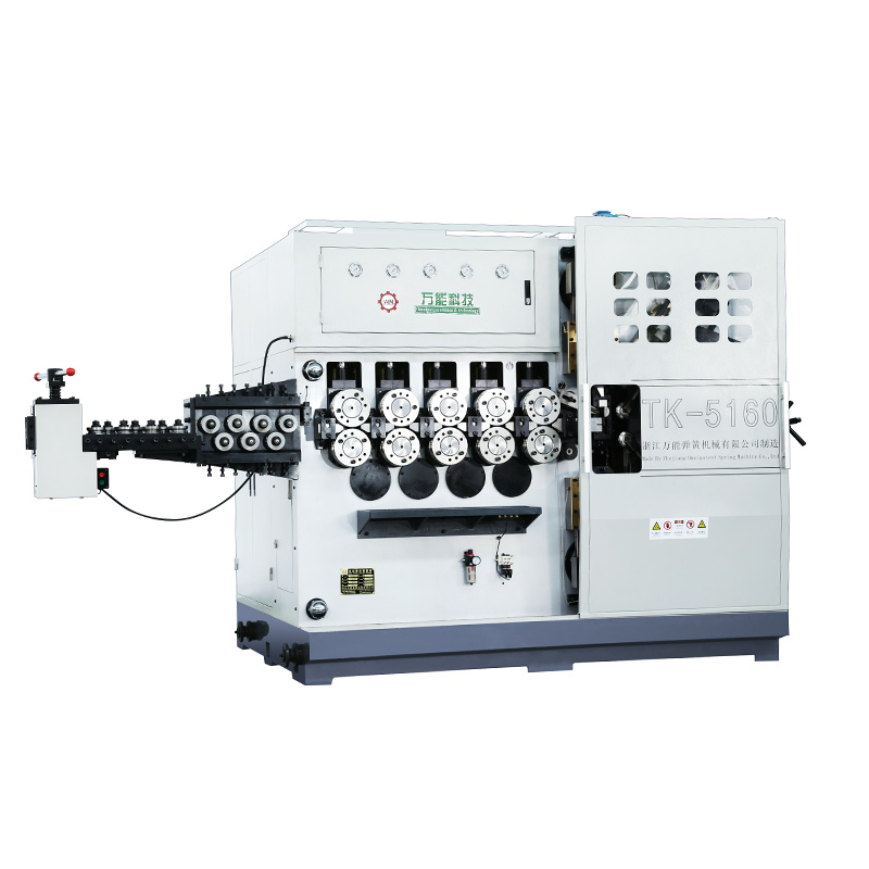
TK-5160 TK-5160 5AXES CNC SPRING COILING MACHINE...
See Details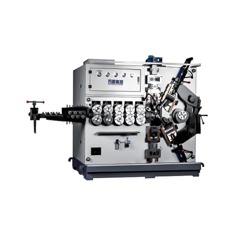
TK-5120 TK-5120 5AXES CNC SPRING COILING MACHINE...
See Details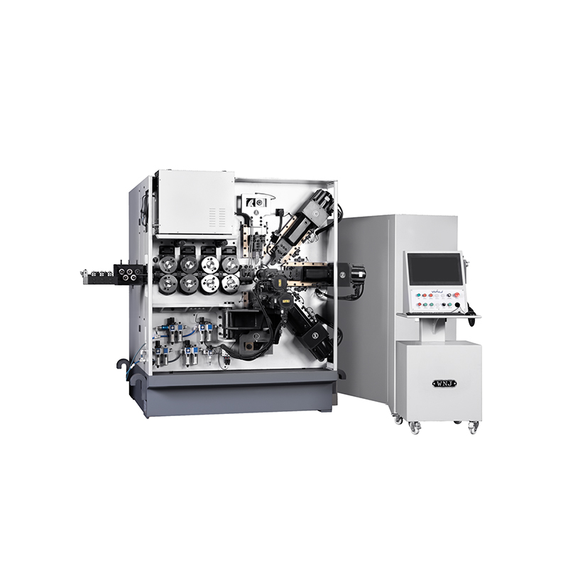
TK TK 10AXES CNC SPRING SCROLL MACHINE...
See Details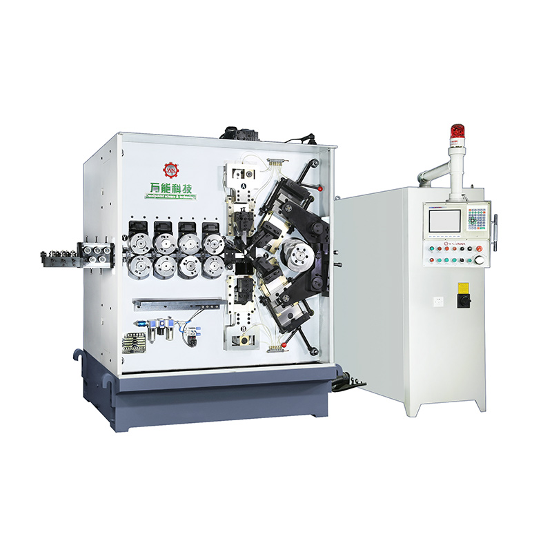
TK-580B、 TK-590 TK-580B、 TK-590 5AXES CNC SPRING COILING MACHINE...
See Details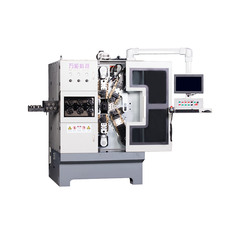
TK-760TK-760 6-7AXES CNC SPRING COILING MACHINE...
See DetailsMobile QR Code

 中文简体
中文简体 English
 русский
 Español