Language

Content
A purchasing team forwards a drawing with three numbers on it: 2.0 mm music wire, eight body coils, and a free leg angle of 90 degrees. Torque at full deflection has to sit between 0.40 and 0.44 N-m, and the part must survive 250,000 open-and-close cycles inside a seat latch assembly. First samples pass every check. Four months later, field returns show legs cracking at roughly 40,000 cycles, and every fracture sits in the same place: the bend where the leg leaves the coil body. Wire chemistry was correct. Coil diameter was correct. The failure was decided by a bend radius nobody had measured.
The direct answer: a torsional spring lives or dies on four variables - wire tensile strength and surface condition, the inside bend radius where each leg exits the body, the bending stress at the inner fiber of that bend, and the stress relief applied after coiling. Change any one of them and the torque curve, the free angle, and the fatigue life all move together.
This guide covers what those four variables mean on the shop floor, the numbers worth writing into a specification, how modern CNC spring machines hold leg angles repeatably, and the failure patterns that tell you which parameter drifted. It is written for the people who have to sign off on a first article inspection and then defend that decision two years later.
A torsional spring stores energy by being twisted, not compressed. The body coils act as a coil of wire in bending rather than in torsion, the two legs transmit the load, and the angle between those legs at rest is the free angle. When a mechanism rotates one leg relative to the other, the spring resists, and the resisting torque rises roughly in proportion to the deflection angle until the material yields.
The rate - torque per degree - scales with the fourth power of wire diameter and falls linearly with the number of active coils and the mean coil diameter. That fourth-power relationship is why a 5 percent wire diameter change can shift torque by more than 20 percent, and why wire diameter certificates matter more for torsion springs than for many other spring types. Elastic modulus of the wire also enters directly: carbon steel runs at about 207 GPa, while 302 stainless sits near 193 GPa, so a straight material swap without a rate recalculation will miss the torque window.
Bending stress at the leg-to-body junction is calculated from the applied moment and the wire section, then multiplied by a correction factor that grows as the bend gets tighter. In plain language: the sharper the corner where the leg leaves the coil, the higher the peak stress, and the sooner a fatigue crack starts on the inside of that corner. Design guidance commonly calls for an inside bend radius of at least half the wire diameter, and fatigue-critical parts frequently use a full wire diameter. Tool marks, die scratches, and grinding burns on the same corner act as crack starters too, which is why surface condition belongs in the specification next to the material grade.
A coil spring can be wound clockwise or counter-clockwise. A torsion spring should be deflected in the direction that tightens the coils, because tightening reduces the inner diameter and keeps the spring seated on its shaft or mandrel. Load it the other way and the body opens, the inside diameter grows, and the spring can walk off its shaft or jam against a housing. This single detail causes a surprising share of assembly-line rejects, and it is usually caught only when the drawing shows the loading arrow and the hand of the wind together.
The table below collects ranges that experienced spring shops treat as working territory rather than hard limits. Values outside these ranges are not automatically wrong, but they deserve a conversation about tooling, inspection cost, and fatigue margin before the drawing is released. For a fuller treatment of the equations behind torque and stress, this torsion spring design equations and materials guide walks through the calculation sequence step by step.
| Parameter | Typical Working Range | Why It Matters |
|---|---|---|
| Wire diameter | 0.2 mm to 6 mm | Above 6 mm, cold coiling and leg bending need higher machine force and careful tool support |
| Spring index (mean diameter divided by wire diameter) | 4 to 16 | Below 4 the wire is over-stressed at the bend; above 16 the coil is unstable and tangles easily |
| Inside bend radius at the leg | 0.5 to 1.0 times wire diameter | Sets the stress correction factor and therefore the fatigue life of the whole part |
| Active body coils | 2 to 20 | Fewer coils raise the rate sharply and concentrate stress |
| Free angle tolerance | plus or minus 3 to 8 degrees | Tighter bands need in-process angle checks and controlled stress relief |
| Torque at rated deflection | plus or minus 10 percent is common | Driven by wire diameter, modulus, and coil count together |
| Stress relief after coiling | About 200 to 300 degrees Celsius for cold-wound carbon and stainless wire | Relieves forming stress without softening the wire below its design load |
Two of these rows interact more strongly than the rest. Index and bend radius together determine whether the leg corner is a smooth transition or a stress riser, and no heat treatment can rescue a geometry that is already over-stressed. When a customer asks for a tighter free angle tolerance, the practical answer is usually better angle control at the machine plus a stable tempering cycle, not a longer inspection bench.
Material choice sets the tensile strength ceiling, the fatigue behaviour, and how much corrosion protection the finished part needs. The grades below cover the overwhelming majority of torsion springs produced on cold-winding equipment.
| Wire Grade | Typical Diameter Range | Best Fit |
|---|---|---|
| Music wire, ASTM A228 | 0.1 mm to 3 mm | Highest tensile strength and best fatigue resistance in small springs; needs plating or coating if moisture is present |
| Oil-tempered MB, ASTM A229 | 0.5 mm to 10 mm | Larger wire sizes where music wire is not stocked; good general-purpose choice |
| Hard-drawn, ASTM A227 | 0.5 mm to 12 mm | Light-duty, low-cycle parts where cost dominates and stress stays low |
| Chrome-silicon, ASTM A401 | 1 mm to 16 mm | High-stress, high-cycle automotive and industrial parts; responds well to tempering after forming |
| Stainless 302 and 304, ASTM A313 | 0.1 mm to 12 mm | Corrosion exposure, food and medical contact, mild temperature service |
| 17-7PH stainless | 0.3 mm to 6 mm | Corrosion resistance plus high strength, often in aerospace and instrument work |
| Phosphor bronze and beryllium copper | 0.1 mm to 5 mm | Electrical conductivity and non-magnetic requirements; modulus around half that of steel |
Three practical notes that save rework. First, a material substitution that keeps the same wire diameter will not keep the same torque, because elastic modulus and allowable stress both change. Second, stainless grades usually carry lower allowable bending stress than music wire of the same diameter, so a corrosion upgrade sometimes forces a diameter increase. Third, request the tensile certificate with each wire lot; a coil-level torsion spring running near its stress limit will show a torque shift as soon as a softer lot arrives at the machine.
On a CNC spring machine, a torsional spring is produced in a short sequence: wire is drawn through feed rolls at a controlled length, wound around a mandrel that sets the inside diameter, spaced by a pitch tool if the body needs gaps, and then the legs are formed, positioned, and cut. Every one of those steps leaves a fingerprint on the finished angle.
Springback is the honest part of the process. Steel wire does not stay where the tool pushes it, and the amount it springs back depends on wire diameter, tensile strength, and how much the leg was bent. Most shops experimentally over-bend the leg by roughly 3 to 8 percent and then lock the corrected tool position into the program. On a camless machine, that correction is a number typed into the program; on a cam-driven machine, it is a mechanical adjustment. The difference shows up directly in changeover time when a family of parts shares one machine.
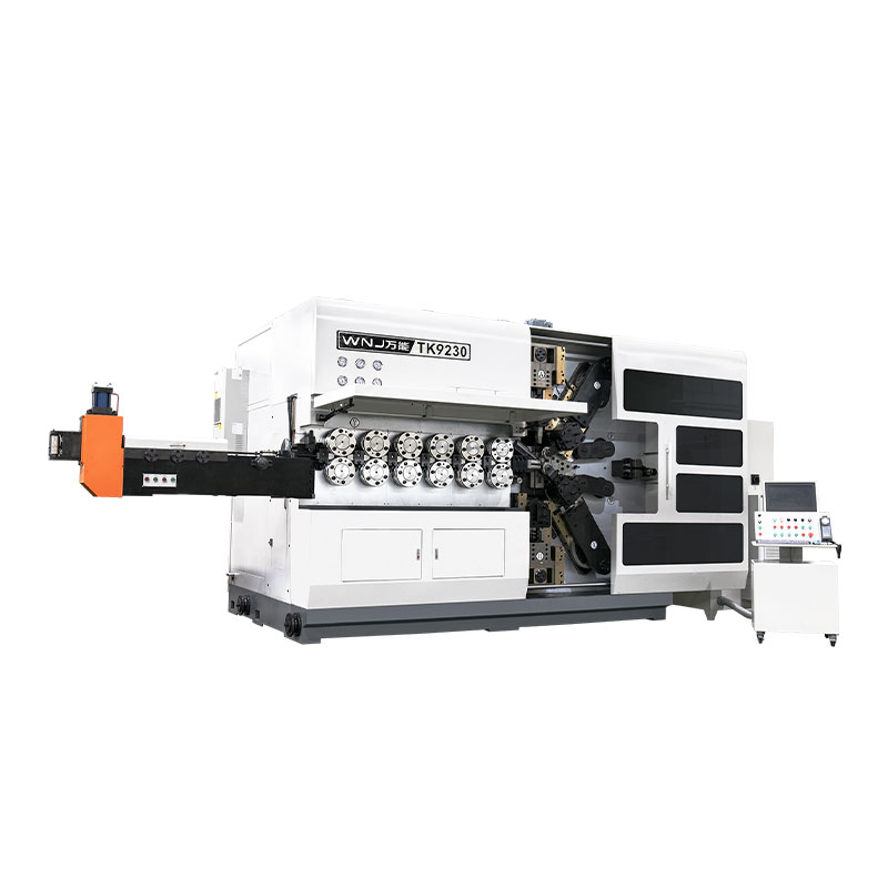
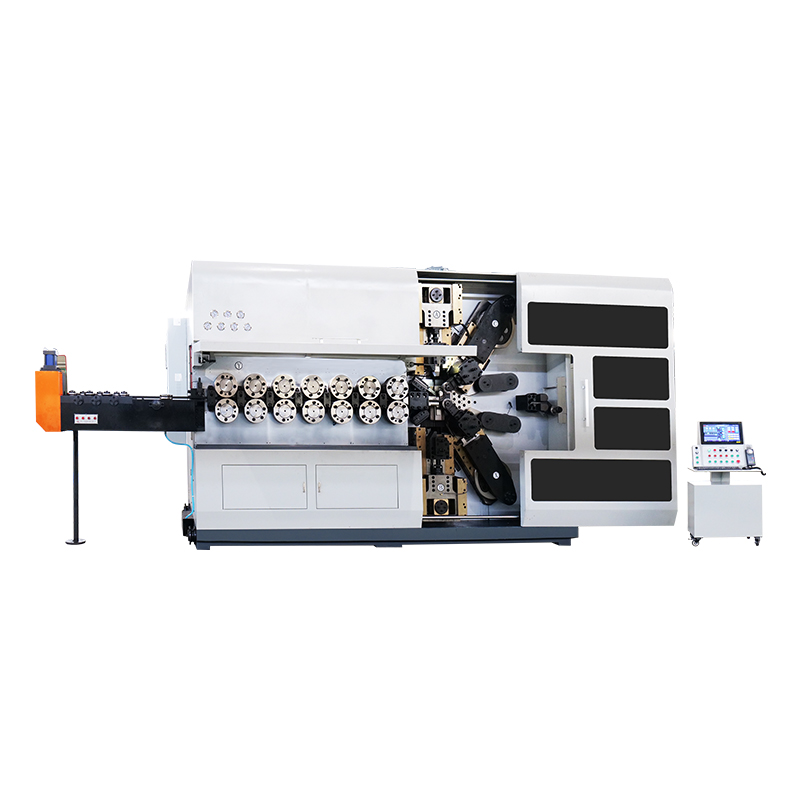
A three-axis machine handles a single straight leg on each side, which covers a large share of latch, clip, and hinge springs. Five-axis machines add independent leg positioning so that legs can sit at different lengths or heights, which is what double torsion springs and offset legs require. Ten- and twelve-axis camless machines form multiple bends, hooks, and even a second spring feature in a single cycle, removing secondary operations that would otherwise need a separate bending station and another fixture.
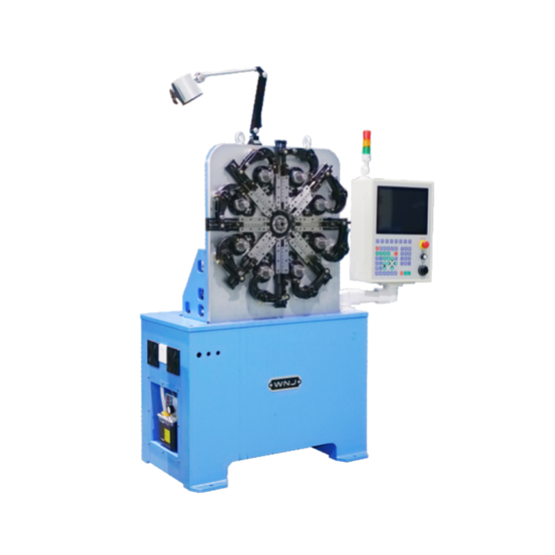 CNC-625D 3AXES CNC SPRING FORMING MACHINEAdditional InformationView Product →
Equipment in this class, such as the CNC625D three-axis CNC spring forming machine, is built around exactly this job: forming the body, bending both legs to angle, and cutting to length in one uninterrupted cycle. The gain is not only speed. Handling a spring twice means two chances to add a scratch at the bend radius, and a scratch at the bend radius is where fatigue cracks begin.
A free angle means nothing unless the measuring method is fixed. The usual convention is to measure the included angle between the two legs when both are held over pins of a specified diameter at a specified distance from the coil. Change the pin diameter and the reported angle changes by several degrees. When a drawing simply states 90 degrees with no pin definition, expect disagreement between the spring maker's inspection sheet and the customer's incoming inspection, even when both parts are identical.
Coiling and leg bending leave residual stresses locked into the wire. Left alone, they shorten fatigue life and make the free angle drift over the first few thousand cycles. A controlled thermal cycle relaxes those stresses, and the temperature window is narrower than most people assume. Run it too cool and the residual stress stays; run it too hot and the wire loses tensile strength, so every spring from that batch measures low on torque.
Wire suppliers publish recommended stress-relief schedules by grade. Cold-wound carbon and stainless springs are generally treated in the region of 200 to 300 degrees Celsius for a defined soak time, while chrome-silicon parts formed in a harder condition may be tempered at higher temperatures to develop their working strength. The schedule matters less than the repeatability: an oven with even air circulation and a recorded cycle produces the same angle and torque on Monday and on Friday.
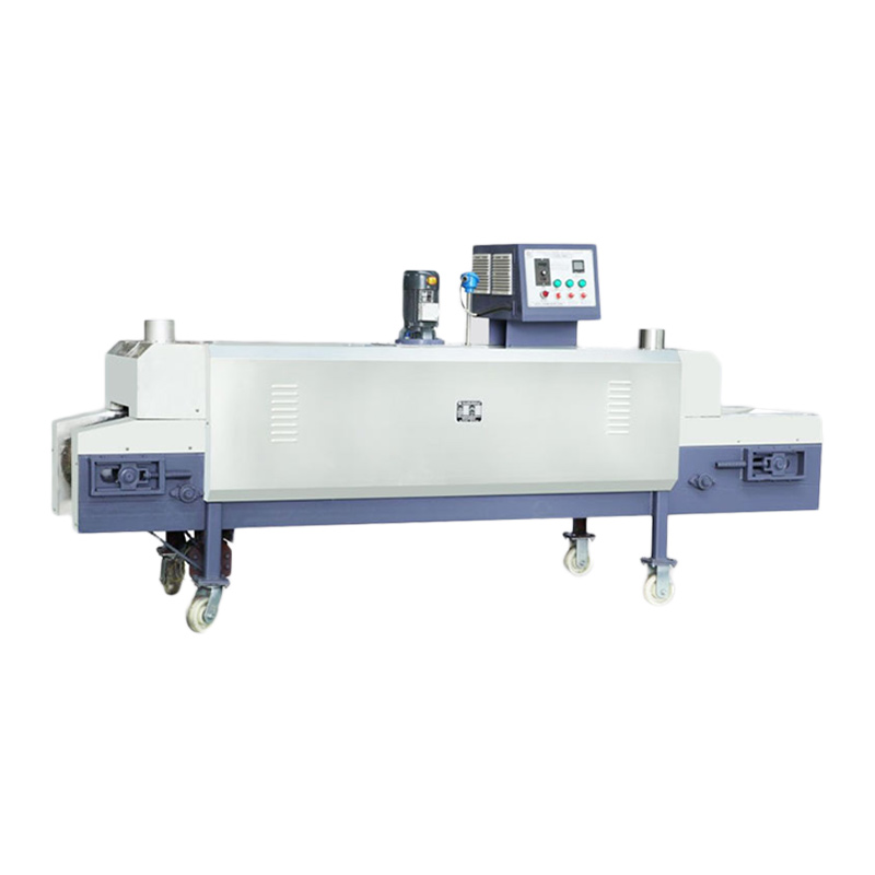 WNJ420 Spring Temper Furnace (Stainless Series)Stainless Series WNJ SPRING TEMPER FURNACEView Product →
Purpose-built tempering equipment, such as the WNJ paint-series spring temper furnace, is designed around that repeatability requirement - a set chamber temperature, a controlled dwell, and consistent airflow across the load. For long or heavy coil springs, a mobile tempering furnace allows the parts to be treated where they are handled rather than moved across the plant, which reduces both distortion risk and cycle time.
A torsion spring is easy to inspect badly. Measuring torque at one point tells you the rate only in combination with a second point; measuring the free angle without a pin definition tells you almost nothing; and inspecting the leg radius with a caliper tells you nothing at all unless the caliper path follows the curve. The plan below is the short list that catches real problems.
Cycle the fatigue sample exactly as the application does, including whether the spring is loaded in the winding direction and whether it travels back to its free angle between cycles. A spring that is held at a preload and oscillated over a small angle behaves very differently from one that is fully released each stroke, and the second case is where most cracks appear.
Torsional springs appear anywhere a mechanism needs a return force around a pivot. In automotive interiors they hold handles, latches, cupholders, and seat mechanisms; in automotive and mobility spring applications the same family of parts also handles pedal return, belt tensioner assists, and small suspension elements where cycle counts run into the millions. Electrical engineering uses them for switch arms and relay contacts, where conductivity and non-magnetic behaviour sometimes push the design toward bronze alloys.
Medical devices use small torsion springs in surgical staplers, clamps, and instrument handles, where the priority is consistent force rather than maximum strength - a surgeon feels a 10 percent torque shift through the handle. Aerospace and military hardware push the other direction, demanding high stress capability in chrome-silicon or 17-7PH with tight traceability. Agricultural and construction machinery use larger wire diameters in dusty, wet environments where the spring is often the least expensive part in the assembly and the least protected. Telecommunications equipment uses tiny torsion springs in connector and fiber-optic hardware, where a few degrees of angle error can change contact pressure.
The common thread across all of these is that the spring is rarely the biggest cost item, but it is frequently the part that determines whether a warranty claim happens. That is the argument for specifying geometry and heat treatment properly at the drawing stage instead of accepting whatever the first tooling setup produces.
Field failures leave a signature. Reading that signature correctly usually saves more time than re-running a full design calculation.
The bend radius is too tight for the wire diameter, the leg is being bent a second time during assembly, or the corner carries a tool mark. Widen the radius toward one wire diameter, move the forming operation earlier in the machine cycle, and inspect the tool that creates the bend.
Insufficient stress relief, or a soak time that was cut to increase throughput. Restore the published schedule for the wire grade and verify torque on parts taken from the middle of the furnace load.
The spring is loaded against the winding direction, so deflection expands the body instead of tightening it. Reverse the wind direction or reverse the loading direction, whichever is cheaper in the assembly.
Legs are being forced past the free angle to fit, which means the assembly takes the spring beyond its rated deflection. Either open up the free angle so the install position sits inside the working range, or reduce the leg length tolerance so the leg does not have to be flexed to enter its slot.
Plating coverage is thinnest exactly where the bend stretches the surface. Specify a coating thickness the process can actually achieve on a curved surface, or switch to a stainless grade and accept the modulus and allowable stress change.
Machine choice follows the part family, not the peak volume. A shop that runs a narrow range of simple torsion springs at high volume gets the best payback from a compact coiler with fast changeover tooling. A shop that quotes mixed orders - forty different torsion springs in a month, each order between 500 and 20,000 pieces - needs forming flexibility and quick programming more than it needs raw cycle speed.
| Machine Type | Shape Capability | Best Suited To |
|---|---|---|
| Three-axis CNC coiler | Round body, straight legs, single bend each side | High-volume latch, clip, and hinge springs with stable geometry |
| Five-axis forming machine | Independent leg angles, offset legs, double torsion bodies | Mixed families where leg geometry varies between orders |
| Ten to twelve-axis camless machine | Multiple bends, hooks, complex three-dimensional legs | Small and medium batches needing fast program changeover |
| CNC wire bending machine | Two and three-dimensional wire forms with open or long legs | Long-leg torsion parts and wire forms that are not true coils |
Camless architecture deserves a specific mention because of how it changes the economics of small batches. With a cam machine, a new leg angle usually means new tooling and a mechanical setup; with a camless machine, it usually means loading a program. For a plant running hundreds of torsion spring variants, that difference determines whether a 2,000-piece order is profitable.
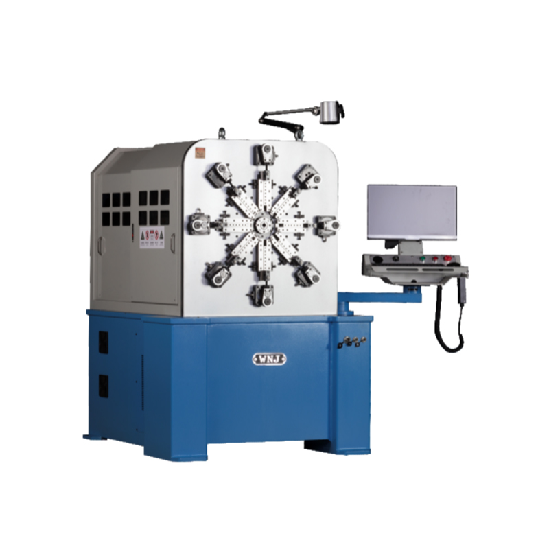 CNC-1225 12AXES CNC SPRING CAMLESS MACHINECNC-1225 12AXES CNC SPRING CAMLESS MACHINEView Product →
A twelve-axis camless platform such as the CNC1225/1235/1250 CNC spring camless machine is aimed squarely at that mixed-batch reality: servo axes are assigned to feeding, coiling, leg forming, and cutting, and switching from one torsion spring to the next is a matter of program and tool position rather than a full rebuild. The practical payoff is that a shop can accept a 1,000-piece order without losing the afternoon to setup.
A torsion bar is a straight length of metal twisted about its own axis, and it stores energy through shear stress. A torsional spring is a coil with two legs, and its body coils work mainly in bending while the legs transmit the moment. The confusion is common because the terms sound similar, but the design calculations, the tooling, and the failure modes are entirely different.
Torque is approximately linear with deflection angle up to the point where the wire begins to yield. The rate depends on the elastic modulus of the wire, the fourth power of wire diameter, the number of active body coils, and the mean coil diameter. Because of that fourth-power term, an accurate wire diameter measurement is more valuable than a more precise angle measurement when you are chasing a torque deviation.
Only one direction is recommended. Loading in the winding direction tightens the coils and shrinks the inside diameter, keeping the spring seated on its shaft. Loading against the winding direction opens the coils, enlarges the inside diameter, and invites the spring to slip, jam, or bind in its housing. Mark the loading direction on the drawing and on the packaging.
The bend is where the highest bending stress meets the smallest radius. Common causes are a bend radius smaller than half the wire diameter, a tool mark acting as a crack starter, an assembly step that flexes the leg beyond its designed angle, and a stress relief cycle that was shortened to boost output. Checking these four items in order resolves most bend failures.
For a cold-wound spring measured over defined pins, plus or minus 5 degrees is a comfortable production target and plus or minus 3 degrees is achievable with in-process checks and a stable tempering cycle. Demanding tighter than 3 degrees usually raises cost faster than it raises assembly yield, because the assembly itself often has more angular variation than the spring.
Small springs can often run without support if the body is short and the deflection is modest. Longer bodies and larger wire diameters tend to buckle or distort sideways under load, so a shaft or a sleeve inside the coil is normal practice. Allow a clearance between the coil inside diameter and the shaft of a few percent of the wire diameter to avoid binding as the coil tightens.
Consumer mechanisms are commonly specified between 50,000 and 300,000 cycles, automotive interior components frequently target 500,000 to 2 million, and safety-related parts push higher still. The number that matters is not the target itself but the stress level at which you claim it. A spring running near the allowable bending stress for its material will not reach a million cycles regardless of how well it is made.
Yes, with the right tooling and axis configuration. Compression springs need pitch control and closed ends; torsion springs need leg forming and angle control. Machines with more servo axes and open programming handle the changeover easily, while very simple coilers are usually dedicated to one family. If your order book mixes spring types, prioritize programming flexibility and tool station access over maximum coiling speed.
Most torsion spring disputes trace back to an incomplete drawing rather than a manufacturing defect. Include the wire grade with its standard reference, the wire diameter with tolerance, the body inside diameter and coil count, the free angle with the pin diameter and pin distance used to measure it, the leg lengths and the inside bend radius on each leg, the torque value with its deflection angle and direction of rotation, the required stress relief or finish, and the cycle life target with the loading condition that defines it.
With those items defined, a spring maker can select the right wire, set the machine axes correctly on the first attempt, apply the correct thermal cycle, and inspect against the same geometry the designer had in mind. Without them, the first article becomes an experiment, and the second article becomes a warranty discussion. Torsion springs are simple parts with sharply interacting variables, and the few minutes spent specifying the details at the drawing stage are the cheapest insurance available in the whole project.
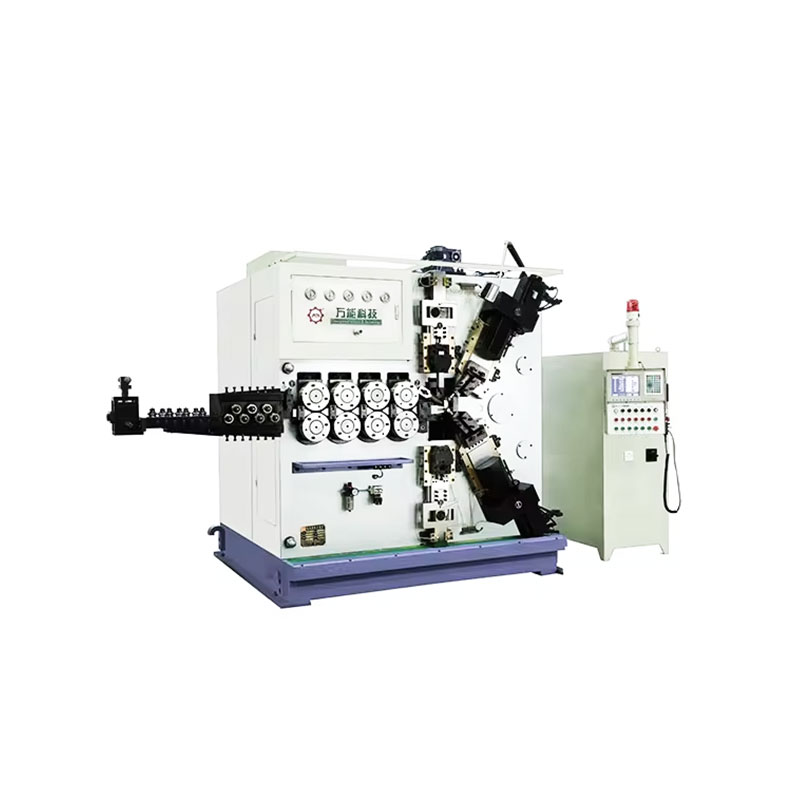
TK-6160 TK-6160 CNC SPRING ROLLING MACHINE...
See Details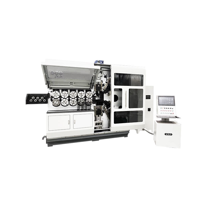
TK-6120 TK-6120 CNC SPRING ROLLING MACHINE...
See Details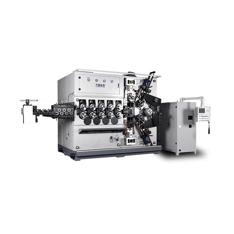
TK-5200 TK-5200 5AXES CNC SPRING COILING MACHINE...
See Details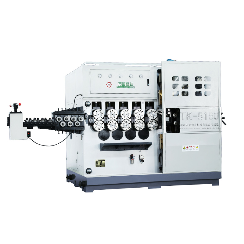
TK-5160 TK-5160 5AXES CNC SPRING COILING MACHINE...
See Details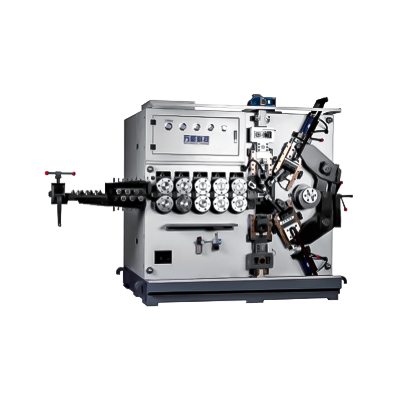
TK-5120 TK-5120 5AXES CNC SPRING COILING MACHINE...
See Details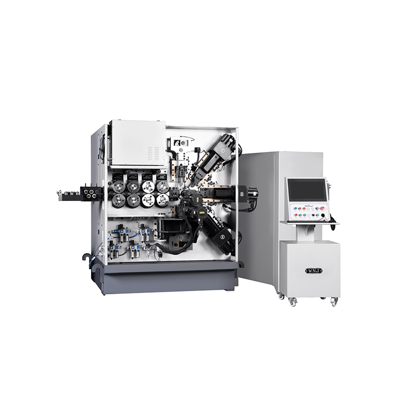
TK TK 10AXES CNC SPRING SCROLL MACHINE...
See Details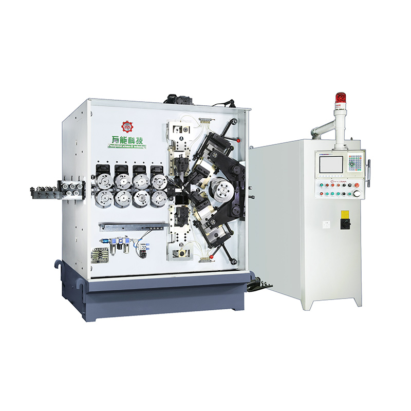
TK-580B、 TK-590 TK-580B、 TK-590 5AXES CNC SPRING COILING MACHINE...
See Details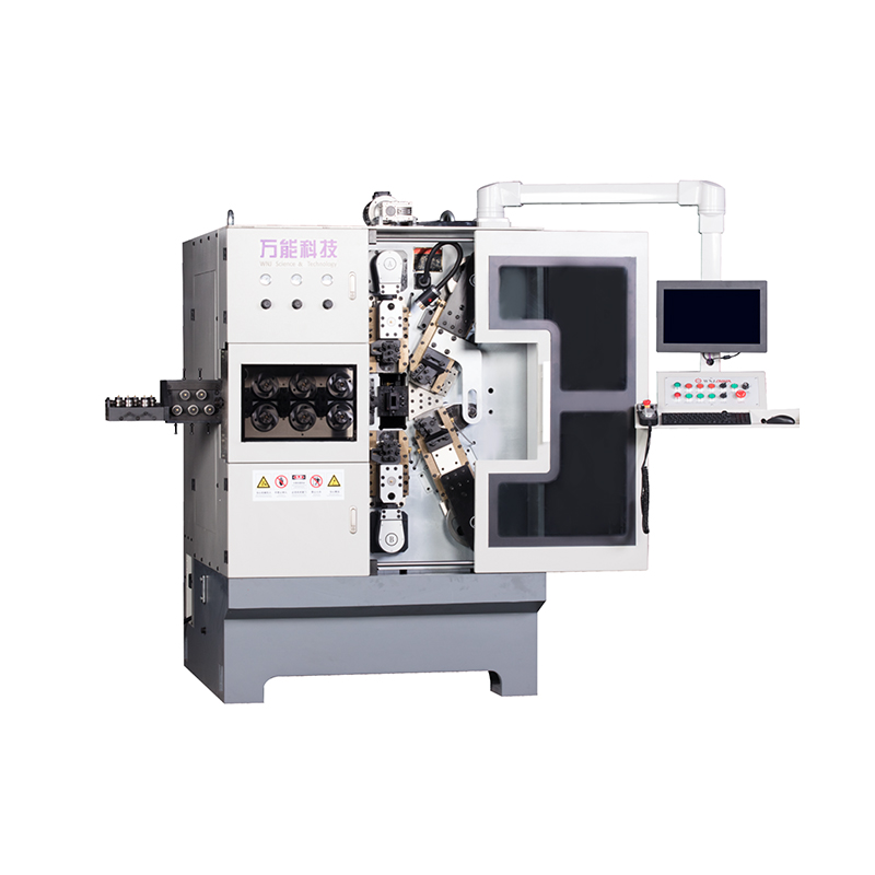
TK-760TK-760 6-7AXES CNC SPRING COILING MACHINE...
See DetailsMobile QR Code

 中文简体
 English
 русский
 Español