Content
A rotational spring — more precisely called a torsion spring — is a mechanical component that stores and releases energy through angular deflection rather than linear compression or extension. When a torque is applied, the spring winds or unwinds along its helical axis, generating a restoring moment proportional to the angle of twist. This is the defining characteristic that separates rotational springs from their tension and compression counterparts.
The operating principle follows a rotational version of Hooke's Law: T = k × θ, where T is the applied torque (in N·mm or lb·in), k is the spring rate (in N·mm/° or lb·in/°), and θ is the angular deflection in degrees or radians. As long as the material stays within its elastic limit, the spring returns to its free position once the load is removed — no permanent set, no energy loss beyond what friction and material hysteresis account for.
In practical terms, this means a rotational spring can replace a motor, counterweight, or pneumatic cylinder in many load-return or torque-biasing applications, often at a fraction of the cost and weight. Engineers across automotive, aerospace, medical device, consumer electronics, and industrial machinery sectors rely on rotational springs precisely because they deliver predictable, repeatable torque without requiring external power.
Not all rotational springs are built the same way, and choosing the wrong type for an application leads to premature fatigue, incorrect torque output, or mechanical interference. The four main categories each have geometries, materials, and production methods that suit specific use cases.
This is the most widely produced rotational spring type. Wire is coiled into a helix with two legs extending outward; when force is applied to those legs, the coil body deflects in torsion. Helical torsion springs are found in clothespins, mousetraps, door hinges, automotive hood latches, and industrial clamps. Wire diameters typically range from 0.1 mm in miniature medical devices to over 20 mm in heavy-duty industrial applications. A modern CNC spring machine can produce these in wire-forming mode at rates exceeding 80 pieces per minute, with leg angle tolerances held to ±1°.
Two coil sections wound in opposite directions are connected at a center point, allowing the spring to generate torque in both rotational directions. This configuration is common in precision instruments and balance mechanisms where bidirectional loading must be accommodated within a compact axial space. Double torsion springs are more complex to manufacture and typically require a spring machine with advanced multi-axis capability and servo-controlled bending heads.
These are flat-wire springs wound in a flat spiral rather than a helix. Commonly called clock springs or power springs, they are central to wristwatches, retractable cable reels, seatbelt retractors, and constant-force actuators. A spiral torsion spring can store significantly more energy per unit volume than a helical torsion spring of equivalent diameter, making them ideal where space is at a premium but high angular travel is needed — sometimes exceeding 720° of rotation. Flat-wire winding requires a spring machine equipped with a dedicated flat-wire feed system and precision tension control.
A torsion bar is a straight rod that twists along its longitudinal axis to provide rotational spring action. Unlike coiled designs, torsion bars offer the highest torsional stiffness-to-weight ratio and are used in vehicle suspension systems, aircraft landing gear doors, and large industrial mechanisms. Common materials include high-alloy spring steel grades such as SAE 5160 and EN 47, with surface shot-peening applied to introduce compressive residual stress and extend fatigue life. Torsion bars are not typically produced on a coiling-type spring machine; they require forging, heat treatment, and precision grinding equipment.
Getting a rotational spring right on the first prototype iteration requires precise specification. Ambiguous drawings lead to costly re-sampling and project delays. The following parameters must be defined before placing an order or programming a spring machine for production.
| Parameter | Definition | Typical Unit | Common Range |
|---|---|---|---|
| Wire Diameter (d) | Cross-section of the spring wire | mm / inch | 0.1 – 25 mm |
| Mean Coil Diameter (D) | Average diameter of the coil body | mm / inch | 1 – 300 mm |
| Number of Active Coils (Na) | Coils contributing to angular deflection | – | 2 – 50 |
| Spring Rate (k) | Torque per unit angular deflection | N·mm/° | 0.001 – 5000 |
| Free Angle (θ₀) | Angle between legs in unloaded state | degrees | 0° – 360°+ |
| Wind Direction | Right-hand or left-hand helix | – | RH or LH |
| Leg Length & Geometry | Straight, hook, bent, or custom | mm | Project-specific |
The spring index C = D/d is a critical ratio to watch. Values below 4 create severe stress concentrations and are extremely difficult to wind consistently on any spring machine. Values above 12 produce flexible, compliant springs but introduce coil instability during winding and in service. Most production engineers target a spring index between 5 and 10 for the best balance of manufacturability and performance.
Wahl's correction factor must be applied to correct the theoretical stress calculation for curvature effects in tightly wound springs. Without it, stress values can be underestimated by as much as 25%, leading to premature fatigue failure in cyclic applications.
Material choice determines fatigue life, corrosion resistance, operating temperature range, and the cost of the finished spring. The wrong material choice is one of the most common causes of field failure in rotational spring applications.
Music wire (ASTM A228) is the workhorse of rotational spring production. With a tensile strength reaching 2,050 MPa for 1.0 mm wire, it offers excellent fatigue performance in static and low-cycle dynamic applications. It is the default material fed through most CNC spring machine setups for general-purpose helical torsion springs. Its limitation is corrosion resistance — uncoated music wire will rust in humid environments within weeks.
For corrosive environments — marine equipment, food processing machinery, medical devices, or outdoor hardware — stainless steel grades are the standard choice. AISI 302 provides good corrosion resistance at a modest cost premium over carbon steel. Grade 316 adds molybdenum for superior resistance to chloride pitting. Precipitation-hardened 17-7 PH stainless offers tensile strengths approaching music wire levels (up to 1,900 MPa) after age-hardening, making it the preferred choice when both high strength and corrosion resistance are non-negotiable. Every reputable spring machine manufacturer ensures their equipment can handle the higher work-hardening rate of stainless steel wire without excessive tool wear.
Chrome-silicon alloy (SAE 9254) and chrome-vanadium (SAE 6150) are used when operating temperatures exceed 120°C or when extremely high fatigue cycles are required. Automotive valve springs, for example, are almost universally made from chrome-silicon wire because it retains its elastic modulus at elevated temperatures. These alloys also respond particularly well to shot-peening, which can extend rotational spring fatigue life by 30–50% under reverse-loading conditions.
Where electrical conductivity, non-magnetic behavior, or sub-zero temperature performance is needed, non-ferrous alloys step in. Phosphor bronze (CuSn8) is a cost-effective option for connector springs and instrument springs operating in humid or mildly corrosive environments. Beryllium copper (CuBe2) delivers the highest fatigue strength of any copper alloy — tensile strengths up to 1,400 MPa after precipitation hardening — and is used in precision test equipment, high-cycle relay springs, and aerospace sensors. Its toxicity during machining and grinding requires strict process controls.
Grade 5 titanium (Ti-6Al-4V) offers roughly half the density of steel with excellent corrosion resistance, making it attractive for aerospace and high-performance motorsport rotational spring applications where weight is critical. Nickel superalloys such as Inconel 718 maintain their spring rate at temperatures above 400°C, a regime where carbon and alloy steels have already lost significant elastic modulus. These exotic materials add significantly to per-piece cost and require specialized spring machine tooling made from carbide or hardened tool steel.
Manufacturing a rotational spring is not simply a matter of bending wire around a mandrel. The geometry must be consistently reproduced across thousands or millions of pieces, with spring rate tolerances typically held to ±10% for standard applications and ±5% for precision parts. This level of consistency is only achievable with modern automated equipment.
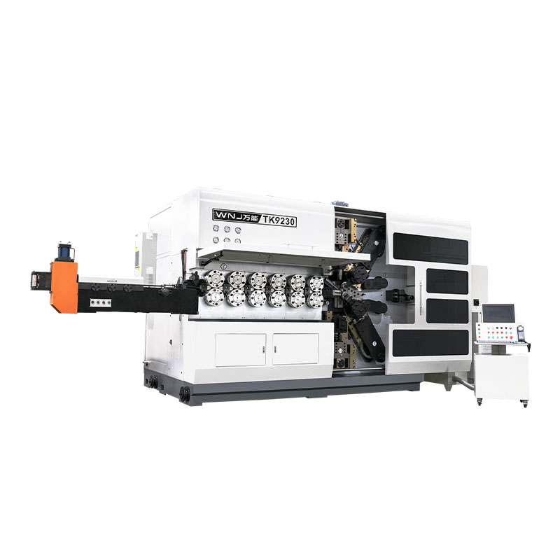
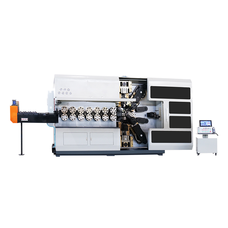
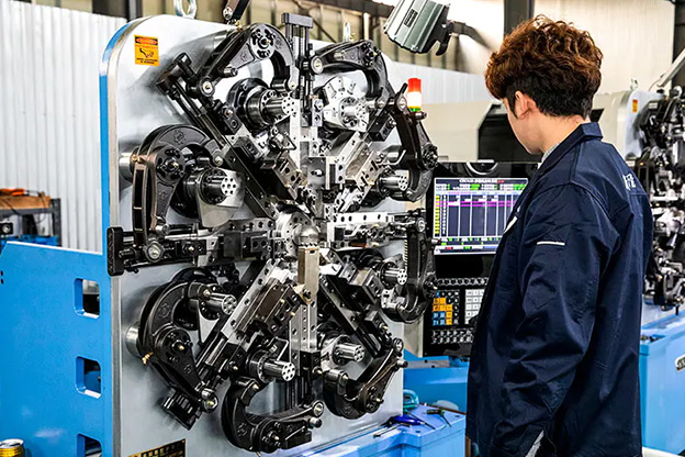
The CNC spring machine is the centerpiece of modern rotational spring production. Unlike older cam-driven machines, CNC spring machines use servo motors and closed-loop feedback to control every bending, cutting, and coiling axis independently. This enables complex geometries — multi-leg torsion springs, tangent-leg ends, radial hook ends, and center-pivot configurations — to be programmed entirely in software and changed over in under 30 minutes. Leading spring machine manufacturers including Wafios, Simplex, Bamatec, and Numalliance offer machines capable of wire diameters from 0.1 mm up to 16 mm, with output rates from 20 to 150 pieces per minute depending on geometry complexity.
The springback phenomenon is the most significant challenge on any spring machine when producing rotational springs. Because the wire attempts to return toward its original straight form after bending, the machine must overbend each feature by a calculated amount to arrive at the correct final angle. Experienced spring machine programmers account for springback based on wire grade, diameter, and coil diameter — a skill that blends engineering calculation with hands-on process knowledge.
There is an important distinction between a coiling spring machine and a wire forming spring machine. A coiling machine produces the helical coil body efficiently at high speed, but it cannot form complex leg geometries without secondary operations. A CNC wire forming spring machine — also called a multi-slide machine or 3D spring machine — handles both the coiling and all leg-bending operations in a single pass, eliminating secondary tooling costs and the dimensional variability introduced by multi-step handling. For rotational spring applications requiring tight leg-angle tolerances, a full CNC wire forming spring machine is generally the preferred production method.
After forming on the spring machine, rotational springs made from hard-drawn or music wire are typically stress-relieved at temperatures between 200°C and 250°C for 20–30 minutes. This step reduces residual forming stresses without softening the material, improving dimensional stability and fatigue life. Springs made from annealed alloy wire — such as chrome-silicon or 17-7 PH stainless — go through a full hardening and tempering cycle after forming, with temperatures and hold times specific to the alloy. Precise temperature control is critical: over-tempering reduces hardness and lowers the spring rate; under-tempering leaves excessive residual stress that promotes early cracking.
Bare steel rotational springs will corrode in most service environments. Common protective treatments include:
The breadth of rotational spring applications reflects how fundamental the need for passive, stored angular energy is across engineering disciplines. The examples below go beyond generic descriptions to show the specific functional requirements each industry demands.
Every modern passenger vehicle contains dozens of rotational springs. Hood and trunk lid counterbalance mechanisms use pre-loaded torsion springs sized to provide near-neutral torque across the full range of lid travel, reducing the effort required for opening and preventing slamming during closing. Throttle return springs and pedal return springs are safety-critical components governed by automotive standards including IATF 16949; they must demonstrate zero fatigue failure over the vehicle's design life — typically 10 years or 150,000 km, whichever comes first. Automotive-grade rotational springs are always sample-tested with torque measurement equipment and undergo 100% free-angle inspection on automated spring machine vision systems integrated into the production line.
Miniature rotational springs in surgical instruments, drug delivery pens, and orthopedic tools operate under strict biocompatibility requirements. Wire diameters frequently fall below 0.3 mm. The spring machine used for these components must maintain wire feed tension within ±0.05 N to avoid variation in coil pitch that would shift the spring rate beyond the ±3% tolerance common in medical applications. Materials are limited to medical-grade stainless steel (AISI 316L or 316LVM) or titanium. Electropolishing is the standard surface finish, removing the thin work-hardened layer and any micro-cracks introduced during spring machine forming, improving fatigue resistance and cleanability.
Flip-phone hinges, laptop screen detents, camera lens mechanisms, and precision measuring instruments all use miniature torsion springs where the torque must be consistent to within fractions of a newton-millimeter. At this scale, variations in wire diameter of just ±0.005 mm — well within a typical wire manufacturer's tolerance — produce measurable spring rate shifts. Spring machine operators at this precision level work with wire supplied to tighter-than-standard tolerances and run statistical process control charts on every production batch. Micro-torsion springs for Swiss watch escapements are among the most exacting rotational spring applications, with wire diameters measured in hundredths of a millimeter and free angles controlled to ±0.5°.
Flight-control actuator return springs, weapon system arming mechanisms, and landing gear door latches rely on rotational springs to provide reliable torque across temperature ranges from −65°C to +150°C or beyond. Every spring in a flight-critical application is individually traced by lot number, material certificate, and heat-treatment batch record. The spring machine program parameters and tool dimensions used to produce each batch are archived as part of the AS9100 quality record. Fatigue testing to 10 million cycles at operational load is common before a new rotational spring design is approved for flight.
Clutch return springs, cam follower return mechanisms, pneumatic valve actuator assists, and robot gripper biasing springs are high-volume industrial applications where rotational springs are often produced in millions of pieces per year. At this scale, raw wire cost and spring machine output rate directly drive unit economics. Coil-per-minute productivity on a modern servo-driven spring machine is typically 40–60% higher than on older cam-driven equipment of equivalent capacity, translating to meaningful cost savings at volume. Close supplier relationships and blanket order programs are common, with suppliers maintaining buffer stock of pre-formed springs to support just-in-time delivery requirements.
Understanding why rotational springs fail is as important as understanding how to design them. Most field failures fall into a small number of predictable categories, nearly all of which are preventable with correct design, material selection, and manufacturing process control.
This is the single most common rotational spring failure. Torsional loading concentrates stress at the inner surface of the coil due to wire curvature, with Wahl's correction factor quantifying the amplification. Springs that are over-deflected beyond the design travel repeatedly — or that are under-specified for their cyclic load — will crack at the inner coil radius, often after a consistent and predictable number of cycles. Prevention: apply Wahl's correction in design calculation, specify maximum allowable deflection clearly on the drawing, and consider shot-peening the finished spring to introduce compressive pre-stress at the high-stress surface.
When a rotational spring is loaded beyond its elastic limit — even once — the coil body takes a permanent angular set and the spring no longer returns to its original free angle. The torque output drops, and if the application depends on a minimum torque level, function is lost. This happens most often when designers use the theoretical maximum angular deflection of a spring without accounting for manufacturing tolerance and assembly variation. A safe design limits working deflection to 75–80% of the theoretical maximum. Pre-setting the spring at the factory — applying maximum deflection intentionally to stabilize the free angle before delivery — is a common mitigation for high-cycle applications.
Acid pickling and electroplating processes introduce atomic hydrogen into the steel wire lattice. In high-strength spring wire — hardness above approximately 40 HRC — this hydrogen diffuses to grain boundaries and stress concentrations, causing delayed brittle fracture under tensile load, sometimes hours or days after the plating process. Torsion springs are particularly susceptible because the inner coil radius is always under residual tensile stress when the spring is in a closed-wound condition. The correct mitigation is a post-plate bake at 190–220°C for a minimum of 4 hours within 1 hour of plating. Consider zinc-nickel or mechanical plating processes that inherently avoid the hydrogen embrittlement risk for the highest-strength rotational spring applications.
A rotational spring in torsion actually decreases in coil diameter as it winds up (for a close-wound right-hand spring loaded in the close-winding direction). If the coils contact an arbor or housing bore prematurely, the effective spring rate changes non-linearly and the leg geometry shifts. Always calculate the wound-down coil diameter at maximum deflection and compare it against the bore diameter with appropriate clearance. On the production end, the spring machine operator must verify that the closed-wound coil diameter falls within the tolerance specified on the drawing — a check that is easily missed if only free-angle and spring-rate measurements are performed during first-article inspection.
A rotational spring that cannot be consistently verified against its specification is a liability risk, not just a quality problem. The industry has developed well-established testing and documentation standards that apply across virtually all production environments.
Torque measurement at one or two specified angular positions is the fundamental acceptance test for any rotational spring. Dedicated torsion spring testers apply a controlled rotation to one leg while the other leg is fixed, reading the generated torque at defined angular positions. Modern computerized torque testers capture the full torque-vs-angle curve, allowing spring rate to be calculated over any angular range. For automotive and aerospace applications, 100% torque testing integrated directly into the spring machine exit conveyor is increasingly the norm, with automatic reject chutes for out-of-tolerance parts.
Free angle — the angle between the two legs with no applied torque — directly determines the installed preload when the spring is fitted into an assembly. It is measured with a protractor gauge or vision system. Leg length and bend angles are verified using optical comparators or coordinate measuring machines for tight-tolerance parts. Modern spring machine manufacturers offer integrated vision inspection systems that measure free angle, coil diameter, free length, and leg geometry at production speed, flagging drifts before they become out-of-tolerance events.
For dynamic applications, sample fatigue testing is performed by cycling the spring between minimum and maximum deflection angles at a defined frequency — typically 500–1,500 cycles per minute on a motorized fatigue rig. The required cycle count depends on the application: consumer products may require 50,000 cycles; automotive safety components often demand 2 million or more. Failure is defined as fracture or a drop in torque output below a defined threshold. S-N curves (stress vs. cycles to failure) are generated for new materials or designs to establish safe working stress limits.
The most widely referenced standards governing rotational spring design and testing include:
Choosing a spring machine for rotational spring production requires matching machine capability to both current production needs and realistic future requirements. The wrong machine choice — either under-specified or over-specified — creates productivity and cost problems that persist for the machine's entire service life, often 15–25 years.
A spring machine that is not maintained consistently will drift out of calibration in ways that are difficult to detect without systematic monitoring. Key maintenance practices for rotational spring production equipment include:
For buyers and procurement engineers, understanding what drives rotational spring unit cost makes it possible to challenge quotations intelligently and collaborate with suppliers on cost reduction without compromising quality.
| Cost Driver | Impact on Unit Cost | Mitigation Strategy |
|---|---|---|
| Wire material (alloy grade) | High | Specify minimum required grade; avoid over-specifying |
| Order volume | Very High | Consolidate orders; use blanket PO with call-off |
| Geometric complexity | Medium to High | Simplify leg geometry where function permits |
| Tolerance tightness | Medium to High | Use DIN/ISO standard tolerances unless precision is critical |
| Surface finish | Low to Medium | Match coating spec to actual corrosion exposure level |
| 100% inspection requirement | Medium | Evaluate whether AQL sampling satisfies quality risk |
| Heat treatment / pre-setting | Low | Include if cyclic loading or dimensional stability is critical |
One of the most effective cost-reduction levers available to buyers is tolerance rationalization. A drawing that specifies ±3% spring rate tolerance forces the supplier to implement 100% torque testing and sort or reject out-of-tolerance parts. Relaxing to ±8% — still acceptable for many applications — may allow acceptance with AQL sampling, cutting inspection cost by 60–70% at volume. Always challenge tight tolerances by tracing them back to an actual functional requirement.
The terms are used interchangeably in engineering practice. "Torsion spring" is the formal technical term used in design standards and material specifications. "Rotational spring" describes the same component's function — it stores energy through rotation rather than linear displacement. Both terms refer to the same family of spring components.
A standard helical torsion spring is designed to be loaded in one direction only — the direction that closes (winds) the coil. Loading in the opposite direction opens the coil and generates very different stress conditions, potentially causing the coils to separate and the spring to buckle or fly off its arbor. For bidirectional torque, a double torsion spring (two coil sections wound in opposing directions) is the correct solution.
Wind direction is specified as right-hand (RH) or left-hand (LH). For a right-hand wound spring, the helix advances clockwise when viewed from the leg end. The correct wind direction depends on how the spring is loaded in the assembly: the load should be applied in the direction that closes (winds) the coil. Specifying the wrong wind direction is one of the most common errors on torsion spring drawings, and a competent spring machine operator or supplier engineer will typically query an ambiguous drawing before proceeding.
Minimum order quantities vary widely by supplier and spring complexity. For a job shop running a CNC spring machine, MOQs for simple torsion springs typically range from 500 to 2,000 pieces for standard wire sizes. High-precision medical or aerospace springs may have MOQs as low as 50–100 pieces due to the high setup and documentation cost. Prototype quantities of 10–50 pieces are available from specialty suppliers at significant per-piece cost premiums. High-volume production programs for automotive applications routinely run in quantities of 100,000 to several million pieces per year.
The elastic modulus of spring steel decreases with increasing temperature. For standard carbon steel wire, the modulus drops by approximately 2% per 50°C rise above room temperature. This means the spring rate falls — the spring becomes softer — at elevated operating temperatures. An application requiring a precise minimum torque at 150°C must be designed with the reduced modulus in mind. At sub-zero temperatures, the modulus increases slightly, stiffening the spring, but low-carbon steels also become susceptible to brittle fracture; stainless steel or titanium is preferred for consistent sub-zero performance.
DIN 2088 and ISO 26909 both provide standard tolerance grades for torsion spring dimensions. Free angle tolerances under standard production conditions typically fall between ±2° and ±5° for most wire diameters. Tighter tolerances — ±1° or better — are achievable with 100% optical inspection on a vision-equipped spring machine but add meaningful cost. Always confirm with the supplier what tolerance their standard production process naturally achieves before specifying tighter-than-needed values on the engineering drawing.
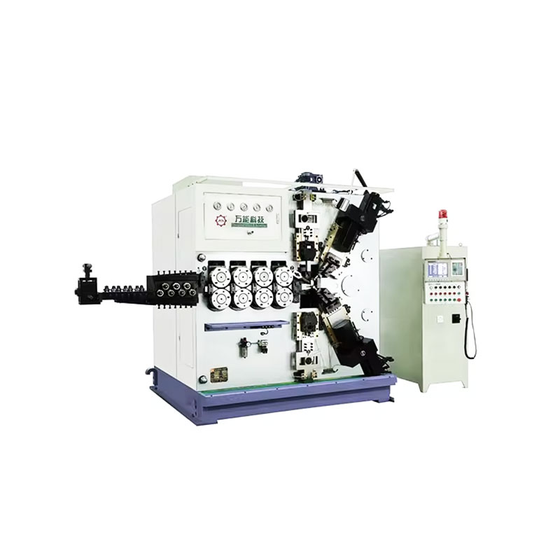
TK-6160 TK-6160 CNC SPRING ROLLING MACHINE...
See Details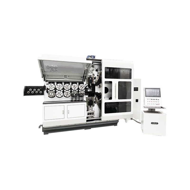
TK-6120 TK-6120 CNC SPRING ROLLING MACHINE...
See Details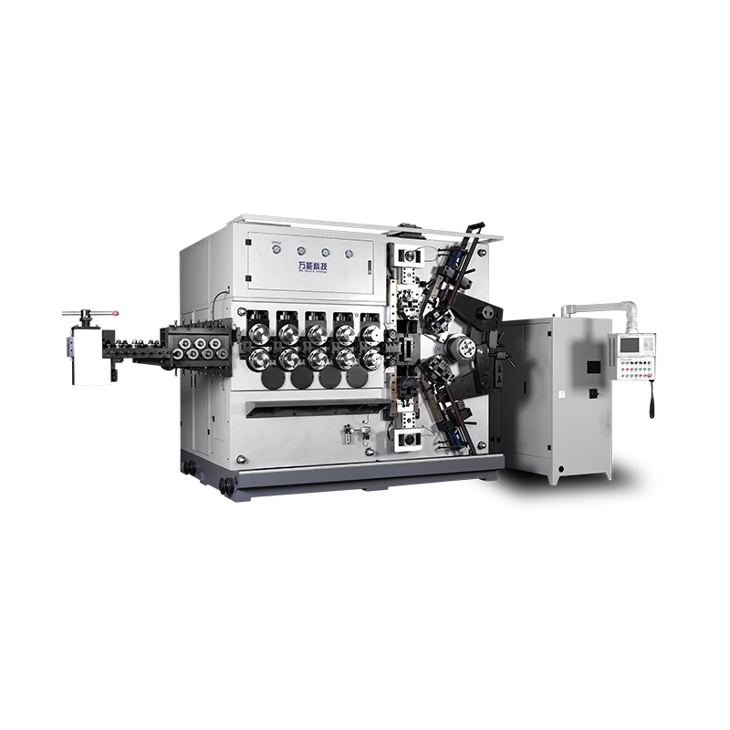
TK-5200 TK-5200 5AXES CNC SPRING COILING MACHINE...
See Details
TK-5160 TK-5160 5AXES CNC SPRING COILING MACHINE...
See Details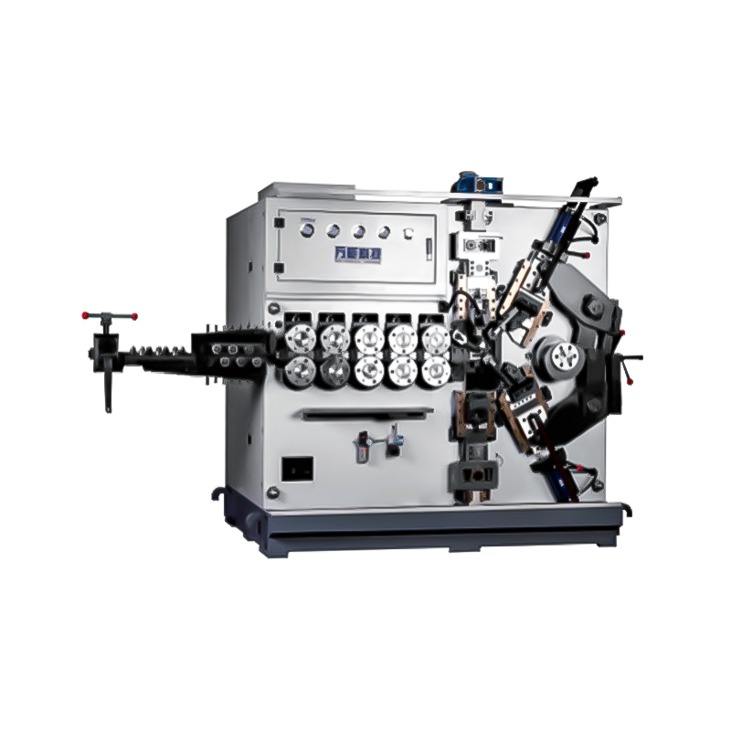
TK-5120 TK-5120 5AXES CNC SPRING COILING MACHINE...
See Details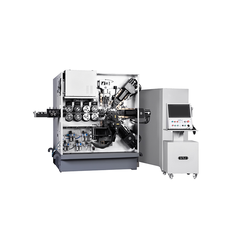
TK TK 10AXES CNC SPRING SCROLL MACHINE...
See Details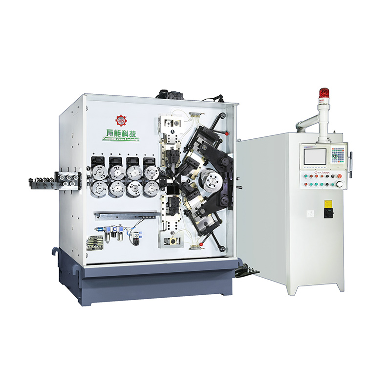
TK-580B、 TK-590 TK-580B、 TK-590 5AXES CNC SPRING COILING MACHINE...
See Details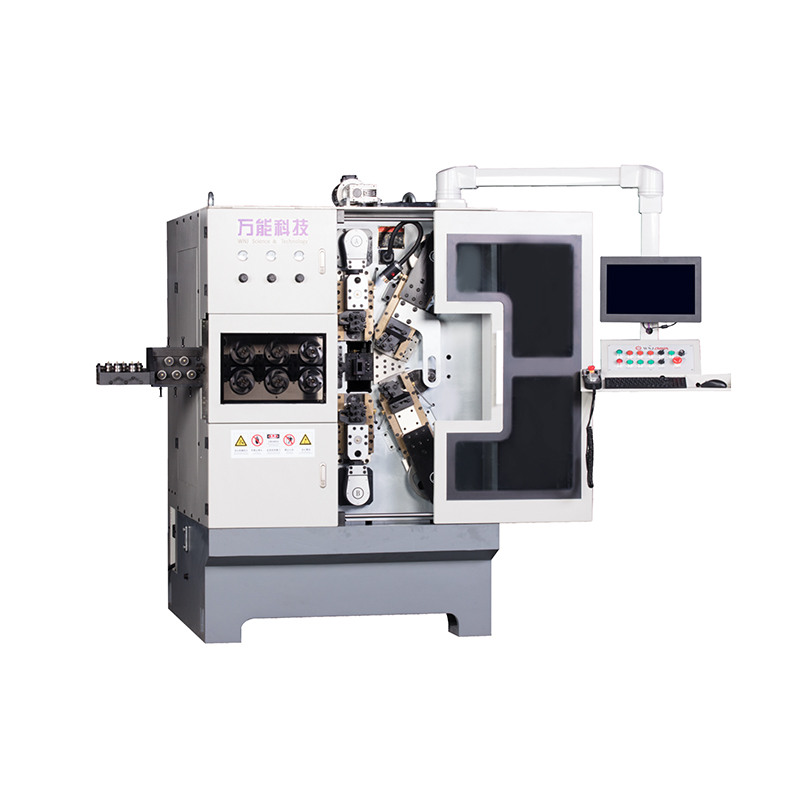
TK-760TK-760 6-7AXES CNC SPRING COILING MACHINE...
See DetailsMobile QR Code

 Language
  中文简体
中文简体 English
 русский
 Español