Content
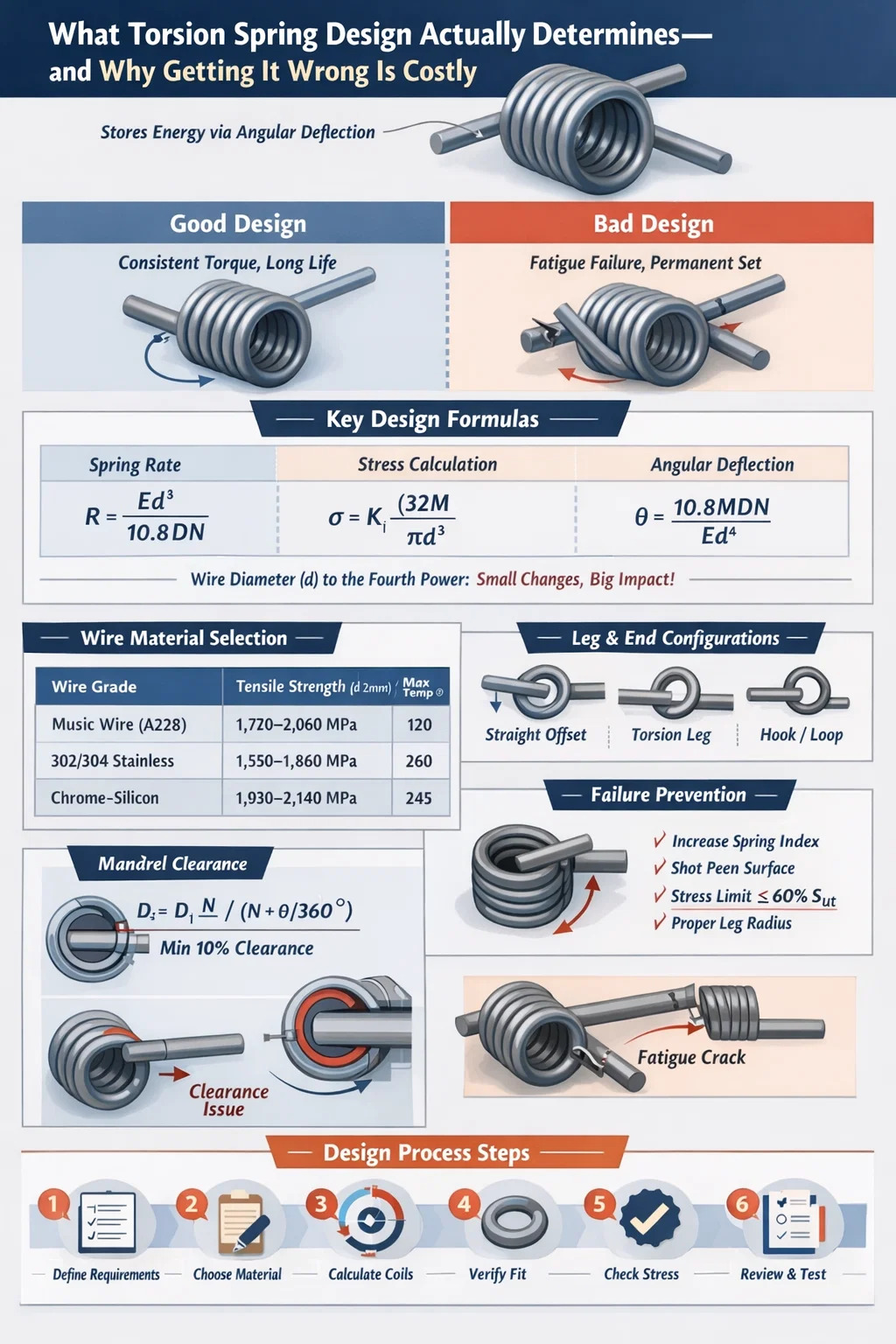
Torsion spring design is the process of specifying the geometry, material, load characteristics, and manufacturing tolerances of a spring that stores energy through angular deflection rather than linear compression or extension. Get the design right, and the spring delivers consistent torque across thousands — or millions — of cycles. Get it wrong, and you face premature fatigue failure, permanent set, or unpredictable torque curves that wreck the downstream mechanism.
The most critical design output is the spring rate (torque per degree of rotation), typically expressed in N·mm/° or lb·in/°. Every other parameter — wire diameter, coil diameter, number of active coils, leg geometry, end configuration — feeds into that number. A torsion spring machine can only produce what the design specifies, so precision in the design phase eliminates costly rework on the production floor.
This article walks through the full design process: from fundamental equations and material selection to manufacturing constraints imposed by torsion spring machines, common failure modes, and practical tolerancing strategies used in high-volume production.
Torsion spring design relies on a set of well-established mechanical equations. Understanding them is not optional — they determine whether your spring survives its operating life or fails in the first few thousand cycles.
The angular spring rate R is calculated as:
R = Ed⁴ / (10.8 D N)
Where E is the modulus of elasticity (MPa), d is the wire diameter (mm), D is the mean coil diameter (mm), and N is the number of active coils. For hard-drawn carbon steel wire, E ≈ 196,500 MPa; for stainless steel 302/304, E ≈ 193,000 MPa; for chrome-silicon (SAE 9254), E ≈ 201,000 MPa.
Notice that wire diameter appears to the fourth power. Increasing d by just 10% raises spring rate by approximately 46%. This is why wire diameter is the most sensitive variable in any torsion spring design — a small tolerance deviation has an outsized effect on final spring rate.
The bending stress in a torsion spring wire is:
σ = K_i × (32M) / (πd³)
Where M is the applied moment (N·mm), d is wire diameter, and K_i is the inner fiber stress correction factor (also called the Wahl factor for torsion springs). K_i accounts for curvature effects and is defined as:
K_i = (4C² - C - 1) / (4C(C - 1))
Where C is the spring index = D/d. For a spring index of 6 (a common value), K_i ≈ 1.24. For a tight coil with C = 4, K_i rises to approximately 1.40. This means a tight-coiled spring sees 13% higher stress at the inner fiber for the same applied moment — a meaningful difference when fatigue life is the design constraint.
Total angular deflection θ (in degrees) is:
θ = 10.8 M D N / (E d⁴)
This equation is the inverse of the spring rate formula. It tells you how much the spring rotates for a given applied torque. In applications like automotive door hinges or window regulators, knowing the exact deflection angle at each torque level is critical for mechanism packaging.
One feature unique to torsion springs: the coil diameter changes as the spring winds or unwinds. When wound in the closing direction (coils tighten), the mean diameter decreases. The new mean diameter D₂ is:
D₂ = D₁ N / (N + θ/360°)
For a spring with 8 active coils rotating 90°, D₂ = D₁ × 8 / 8.25 = 0.970 × D₁ — a 3% reduction. If the spring operates over a mandrel, the designer must verify that D₂ still provides adequate clearance; interference at maximum deflection causes catastrophic torque spikes and premature failure. Standard design practice is to maintain at least 10% clearance between the deflected inner coil diameter and the mandrel outer diameter.
Material choice is inseparable from torsion spring design. The wire must deliver the required tensile strength, endurance limit, and corrosion resistance across the operating temperature range, while remaining compatible with the torsion spring machine's forming capabilities.
| Wire Grade | Tensile Strength (d=2mm) | Max Temp (°C) | Typical Use |
|---|---|---|---|
| Hard-drawn (ASTM A227) | 1,380–1,650 MPa | 120 | General purpose, static loads |
| Music wire (ASTM A228) | 1,720–2,060 MPa | 120 | High-cycle fatigue, precision |
| 302/304 Stainless (ASTM A313) | 1,550–1,860 MPa | 260 | Corrosive environments |
| 316 Stainless (ASTM A313) | 1,480–1,790 MPa | 315 | Marine, chemical exposure |
| Chrome-silicon (SAE 9254) | 1,930–2,140 MPa | 245 | High stress, elevated temp |
| Inconel 718 | 1,240–1,380 MPa | 600 | Aerospace, gas turbines |
For most industrial applications — door hinges, latches, retractors, and electrical connectors — music wire (ASTM A228) is the default choice. Its high tensile strength and consistent surface quality support fatigue lives exceeding 500,000 cycles at stress levels up to 70% of the ultimate tensile strength. Hard-drawn wire costs 10–15% less but has a rougher surface finish and more tensile strength variability, making it more suitable for static or low-cycle applications.
Chrome-silicon wire, while more expensive, is the standard choice for automotive valve springs and brake return springs where operating temperatures reach 200–240°C and stress relaxation must be minimized. It is also more demanding for the torsion spring machine because its higher hardness accelerates tooling wear — a factor to discuss with the manufacturer during design review.
Phosphor bronze and beryllium copper appear in electrical connector springs where conductivity matters alongside mechanical performance. Beryllium copper in particular, while expensive, achieves tensile strengths approaching 1,400 MPa and maintains excellent set resistance, making it suitable for precision instruments with tight torque tolerances over extended service life.
The end configuration of a torsion spring — how the legs are shaped, where they contact the mating parts, and what geometry they follow — directly affects three things: the effective number of active coils, the stress concentration at the leg-body junction, and what the torsion spring machine can realistically form.
The effective number of active coils N_a includes a contribution from the legs. For straight legs, the standard approximation adds L/(3πD) to the body coil count, where L is the total length of both legs. For a spring with a mean coil diameter of 20 mm and two 30 mm legs, this adds approximately 30/(3π×20) ≈ 0.16 coils — a small but non-trivial correction when tight spring rate tolerances (±5% or better) are required.
Ignoring this correction leads to systematic spring rate errors that become apparent during first-article inspection, requiring coil count adjustments and additional CNC torsion spring machine setup time.
A torsion spring machine — specifically a CNC coiling machine with torsion spring capability — forms wire by bending it around a coiling mandrel while simultaneously shaping the legs and end features. Understanding what the machine can and cannot do is essential at the design stage, before tooling is cut.
Standard CNC torsion spring machines handle wire diameters from approximately 0.10 mm to 16 mm, depending on the machine class. Entry-level CNC coilers cover 0.3–3.5 mm; heavy industrial machines handle 3–16 mm wire. Spring index (D/d) is practically constrained between 4 and 16 for most production runs:
The sweet spot for torsion spring machine production is C = 6 to C = 12, where forming forces are manageable, tool wear is predictable, and dimensional tolerances are achievable at high production speeds.
Modern CNC torsion spring machines — such as those from Wafios, Numalliance, or Simplex — operate with 4 to 8 controlled axes. Key capabilities include:
The free angle — the angle between the two legs in the unloaded state — is one of the most challenging parameters to control. Free angle tolerance of ±3° to ±5° is standard production capability; ±1° to ±2° is achievable with premium CNC torsion spring machines and process qualification, but at a higher cost per piece. Designers should specify the tightest tolerance they actually need, not the tightest they think is possible — over-specifying free angle tolerance can double or triple the part cost without improving product function.
After forming, torsion springs made from pre-hardened wire (music wire, hard-drawn, stainless) undergo a low-temperature stress relief bake — typically 175–230°C for 20–30 minutes. This reduces residual stresses induced during coiling, stabilizes the free angle, and reduces set in service. Chrome-silicon and chrome-vanadium springs are formed from annealed wire and then oil-quenched and tempered to final hardness after coiling, which gives more control over material properties but requires additional process steps on the torsion spring machine line.
Shot peening, applied after heat treatment, induces compressive residual stresses on the wire surface, raising the fatigue endurance limit by 20–30% for springs operating in reversed bending. For torsion springs in high-cycle applications (above 500,000 cycles), shot peening is almost always specified despite adding 15–25% to part cost, because the alternative — fatigue failure in the field — is far more expensive.
Fatigue failure is the dominant failure mode for torsion springs under cyclic loading. It initiates at the inner coil surface (where bending stress is highest due to curvature) or at the leg-body junction (a stress concentration point). Predicting fatigue life requires understanding both the stress amplitude and the mean stress.
The Modified Goodman criterion relates allowable stress amplitude σ_a to mean stress σ_m:
σ_a / S_e + σ_m / S_ut = 1
Where S_e is the endurance limit and S_ut is the ultimate tensile strength. For music wire, S_e ≈ 0.45 × S_ut for polished specimens. Surface finish correction factors reduce this to approximately 0.35–0.38 × S_ut for production wire with standard surface quality.
The Gerber parabola is sometimes used as an alternative to the Goodman line because it fits empirical spring fatigue data more closely at high mean stress levels. However, Goodman remains more conservative and is preferred for safety-critical applications.
In practical torsion spring design, the following stress ratio targets provide reliable fatigue performance:
These targets must be calculated using the stress-corrected formula with the Wahl factor. Applying the nominal bending stress equation without curvature correction underestimates actual wire stress by 15–35% depending on spring index — a potentially catastrophic error in high-cycle design.
Torsion springs under sustained load can exhibit permanent set — a permanent change in free angle over time due to creep in the wire material. Permanent set is temperature-dependent and becomes significant above 100°C for carbon steel wire. The maximum allowable sustained stress to limit set to less than 2% over 1,000 hours at room temperature is approximately 65% of S_ut for music wire and 70% for chrome-silicon.
For applications where the spring is held in a compressed position (as in many automotive and appliance mechanisms), the designer must verify that the sustained stress at maximum deflection does not exceed these limits. Failure to do so results in torque decay over the product's service life — a common field complaint that traces directly back to torsion spring design oversight.
Specifying tolerances on a torsion spring drawing is where engineering judgment intersects with manufacturing cost. Every tolerance tighter than standard production capability requires additional process controls, increased inspection frequency, or slower torsion spring machine cycle times — all of which add cost.
| Parameter | Standard Tolerance | Tight Tolerance (Premium Cost) |
|---|---|---|
| Wire diameter | Per ASTM wire standard (typically ±1–2%) | ±0.5% (requires certified wire lot) |
| Mean coil diameter | ±2–3% | ±1% |
| Number of coils | ±0.25 coils | ±0.1 coils |
| Free angle | ±5° | ±2° |
| Spring rate | ±10% | ±5% |
| Torque at test angle | ±10% | ±5% |
| Leg length | ±1.0 mm | ±0.5 mm |
| Body length (closed coil) | ±0.5 mm | ±0.2 mm |
The most important tolerance to specify correctly is the torque at a defined test angle, not the spring rate in isolation. A torque tolerance at a specific angle is more directly linked to product function — it tells the manufacturer exactly what the spring must deliver at the point in its travel that matters to the assembly. Spring rate alone doesn't tell the story if the free angle varies.
A common and effective approach is to specify: (1) torque at minimum working angle, (2) torque at maximum working angle, and (3) free angle with a wide tolerance. This functional specification gives the torsion spring machine operator maximum freedom to optimize the forming process while ensuring the spring performs correctly in the assembly.
A torsion spring drawing should always specify:
Omitting wind direction from a drawing is one of the most common and costly errors in torsion spring procurement. A right-hand torsion spring wound in the closing direction generates increasing torque as it closes — if the assembly requires closing torque from a left-hand spring, the mechanism will work in reverse or not at all.
Understanding failure modes is not post-mortem engineering — it is a design input. Each failure mode maps to specific design decisions that can prevent or mitigate it.
The highest bending stress in a torsion spring occurs at the inner fiber of each coil due to the curvature effect (captured by the Wahl factor). Fatigue cracks initiate here and propagate transversely across the wire diameter, resulting in sudden fracture. Prevention strategies:
Set manifests as a reduction in free angle over time, reducing the torque delivered at the working angle. The root cause is sustained stress exceeding the material's elastic limit at operating temperature. Prevention: keep sustained stress below 65% S_ut for carbon steel, use preset springs (pre-deflected beyond the maximum working angle during manufacture to induce favorable residual stresses), or specify a higher-alloy wire with better relaxation resistance.
As the spring deflects in the closing direction, the coil inner diameter decreases. If the spring is mounted over a mandrel with insufficient clearance, the coils contact the mandrel — generating friction, heat, and unpredictable torque spikes. In severe cases, the spring seizes on the mandrel entirely. The fix is straightforward in design: calculate the minimum coil inner diameter at maximum deflection using the diameter-change formula and ensure the mandrel OD is at least 10% smaller. However, this requires the designer to know the maximum operating angle at the design stage.
The transition from the coil body to the straight leg is a geometric discontinuity that creates stress concentration. The magnitude depends on the sharpness of the bend. A minimum bend radius of 1.5d at the leg root is good design practice — radii smaller than this dramatically increase the stress concentration factor. When the torsion spring machine forms the leg, the operator adjusts the tool to achieve this minimum radius. If the designer draws a sharp corner at the leg root, the machine will produce a sharp corner, and fatigue failure will occur at that location rather than in the coil body where the stress analysis predicts it.
The most efficient torsion spring designs are developed collaboratively between the engineer and the spring manufacturer — specifically, involving the team operating the torsion spring machine early in the design process, before the drawing is finalized.
Key DFM considerations to raise with the manufacturer:
The engineer who treats the spring manufacturer as a pure commodity supplier — providing a complete drawing with no discussion — consistently gets suboptimal results. The engineer who involves the torsion spring machine team in design review gets springs that are easier to make, more consistent, and less expensive at production volumes.
Torsion spring design principles play out differently across industries. Here are concrete examples of how application context shapes design decisions.
Typical specification: torque of 8–12 N·m at 75° deflection, 500,000 cycle life, operating temperature −40°C to +80°C. Wire diameter 4–6 mm, chrome-silicon alloy, shot peened, zinc phosphate coated. The torsion spring machine must produce consistent free angle to ±3° because the door detent feel is sensitive to torque variation at the intermediate check position (typically 30–45°). These springs are produced at high volume — hundreds of thousands per year — justifying dedicated torsion spring machine tooling and in-process torque testing at 100% of parts.
Typical specification: torque of 0.5–2 N·mm at 30° deflection, 50,000+ cycle life, phosphor bronze or beryllium copper, gold flash plated. Wire diameter 0.15–0.5 mm. At this scale, the torsion spring machine must maintain wire feed precision to ±0.02 mm to achieve the ±5% torque tolerance required. Free angle tolerance of ±3° translates to a torque variation of ±10–15% at the working angle, which must be tight enough to ensure reliable electrical contact force without over-stressing the mating pin.
Surgical instruments and implantable device mechanisms use torsion springs made from 316L stainless steel or MP35N alloy. Torque tolerances of ±3–5% are typical. Every spring is 100% inspected. Traceability requirements mean each production lot is linked to a specific wire heat number and torsion spring machine batch record. These requirements add significantly to cost but are non-negotiable given the regulatory environment. Wire diameters typically range from 0.25 mm to 2.0 mm depending on the application.
Residential garage door torsion springs are large (wire diameter 4–8 mm, mean coil diameter 50–75 mm) and designed for 10,000 to 30,000 cycles of life. They are wound in opposite pairs on a central shaft, balancing the door weight. The spring rate must match the door weight and height within ±10% or the door will not balance correctly. These springs are produced on large industrial torsion spring machines in high volume, sold as commodity items, and are one of the most common household spring failures — not because they are poorly designed, but because they are designed to a cost target that limits cycle life.
Bringing the design process together into a structured workflow prevents the common mistake of iterating late in development when changes are expensive.
Following this sequence consistently avoids the most expensive category of spring design errors: discovering dimensional or performance problems during assembly validation, when changing the spring design requires re-qualifying the torsion spring machine setup and potentially redesigning mating parts.
TK-6160 TK-6160 CNC SPRING ROLLING MACHINE...
See Details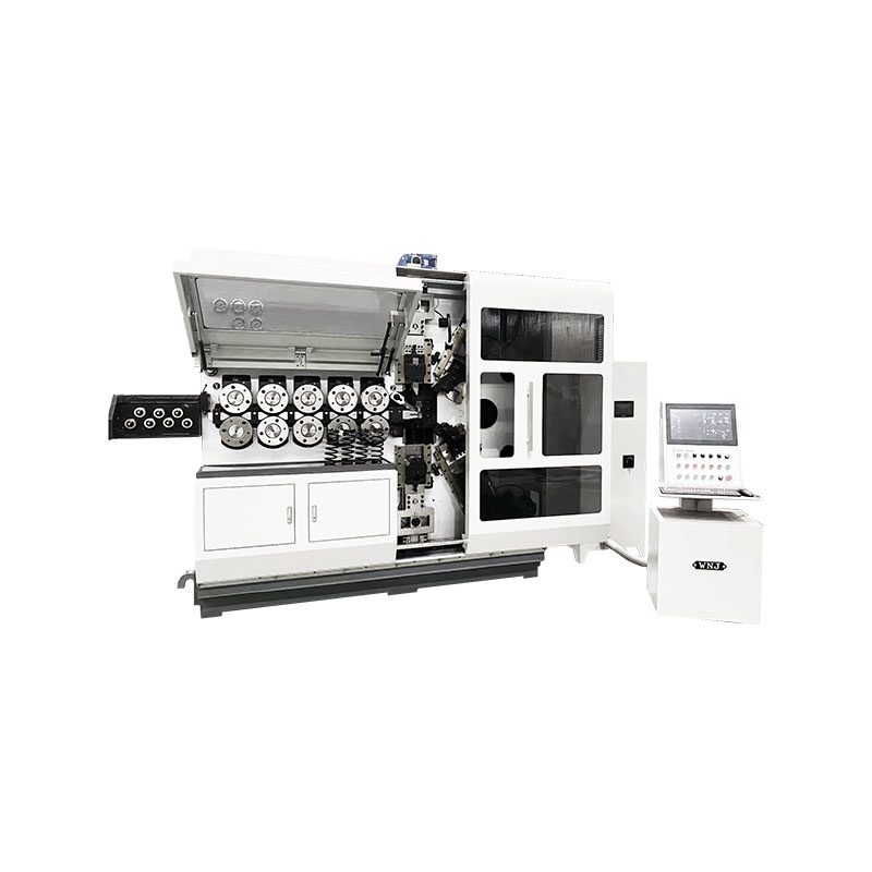
TK-6120 TK-6120 CNC SPRING ROLLING MACHINE...
See Details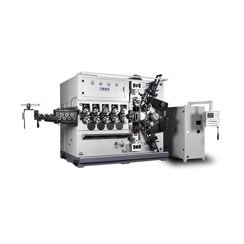
TK-5200 TK-5200 5AXES CNC SPRING COILING MACHINE...
See Details
TK-5160 TK-5160 5AXES CNC SPRING COILING MACHINE...
See Details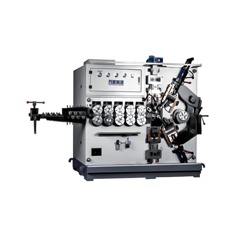
TK-5120 TK-5120 5AXES CNC SPRING COILING MACHINE...
See Details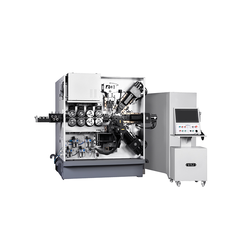
TK TK 10AXES CNC SPRING SCROLL MACHINE...
See Details
TK-580B、 TK-590 TK-580B、 TK-590 5AXES CNC SPRING COILING MACHINE...
See Details
TK-760TK-760 6-7AXES CNC SPRING COILING MACHINE...
See DetailsMobile QR Code

 Language
  中文简体
中文简体 English
 русский
 Español