Content
Springs are made by coiling, bending, or stamping metal wire or strip stock into a shape that stores and releases mechanical energy. The most common method is coil winding — feeding wire through a CNC spring machine that bends it around a mandrel at a precisely calculated pitch and diameter. For high-volume production, this process runs at speeds between 50 and 400 parts per minute depending on spring size and material.
Whether you are prototyping a single part in a workshop or running thousands of units on a commercial spring coiling machine, the core steps are the same: select the right wire, set the geometry, wind or form the spring, heat-treat it, and finish the surface. Each stage has tolerances that directly affect the spring's load, fatigue life, and dimensional consistency.
The sections below break down each step in detail — with real measurements, material choices, and machine settings — so you can produce springs that perform reliably from the first coil to the last.
Understanding which type of spring you need determines the manufacturing process, the tooling, and the machine configuration. There are five major categories used across industrial and consumer applications.
The most common type. Round wire is wound into a helix with an open pitch so the spring compresses under axial load. Made on a CNC coil spring machine with pitch tool adjustments. Free length tolerances are typically ±1–2% of the nominal length.
Wound with close coils and initial tension so coils press together at rest. Hooks are formed on each end by the spring machine immediately after winding. Hook geometry — full twist, half twist, or extended — is set in the machine program.
Resist rotational force. Wound with close or open coils, with legs that extend tangentially. A torsion spring machine bends the legs to precise angles — commonly 90°, 180°, or custom angles within ±1°.
Stamped or bent from flat strip stock. Automotive leaf springs use stacked plates clamped at the center. Smaller flat springs for electronics are stamped on progressive die presses at rates up to 800 strokes per minute.
Conical washers that stack in series or parallel. Formed by blanking a washer from sheet and pressing it into a cone profile. Load capacity varies dramatically with cone height — a 1 mm height difference can change load by 30–50%.
Material selection is not optional guesswork — the wrong alloy will cause premature fatigue, corrosion failure, or dimensional drift under temperature. The table below covers the most commonly specified spring materials across industries.
| Material | Standard | Tensile Strength | Max Temp (°C) | Best For |
|---|---|---|---|---|
| Music Wire (High Carbon) | ASTM A228 | 1700–2400 MPa | 120 | General purpose, high-cycle |
| Hard Drawn Wire | ASTM A227 | 1200–1900 MPa | 120 | Static or low-cycle loads |
| Stainless Steel 302/304 | ASTM A313 | 1300–2000 MPa | 260 | Corrosive environments |
| Stainless Steel 316 | ASTM A313 | 1100–1800 MPa | 316 | Marine, chemical exposure |
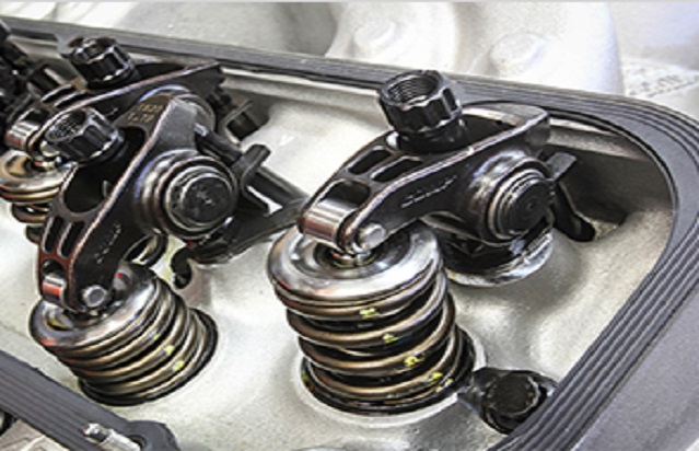
| Chrome Silicon (SiCr) | ASTM A401 | 1900–2200 MPa | 245 | High-stress valve springs |
| Inconel 718 | AMS 5596 | 1240–1450 MPa | 700 | Aerospace, extreme heat |
| Phosphor Bronze | ASTM B159 | 700–1100 MPa | 95 | Electrical contacts, non-magnetic |
Music wire (ASTM A228) covers roughly 70% of all compression spring production worldwide due to its high tensile strength and consistent surface quality. Chrome silicon alloys are used where operating stress exceeds 45% of tensile strength or where the spring cycles more than 10 million times.
Wire diameter drives tensile strength: a 0.5 mm music wire has tensile strength near 2400 MPa, while a 6 mm wire of the same alloy drops to around 1700 MPa. This inverse relationship is built into every spring design equation and must be accounted for before setting up the spring machine.
Running a spring machine without first calculating the key parameters is how you waste material and produce out-of-spec parts. The following formulas are the foundation of every compression spring design.
Where G = shear modulus (~80,000 MPa for steel), d = wire diameter, D = mean coil diameter, Na = number of active coils. A typical automotive valve spring with d = 3.5 mm, D = 28 mm, and Na = 8 produces a rate around 28 N/mm.
C = D/d (spring index). Springs with an index below 4 experience high stress concentration at the inner coil — the Wahl factor corrects the shear stress calculation. Most springs are designed with C between 6 and 12.
Nc = number of inactive (closed) coils, δ = pitch × Na. For a compression spring with 2 closed ends, Nc = 2. Free length directly sets the machine stop position during winding on a CNC spring coiling machine.
Solid length is the compressed height when all coils touch. Always verify that the working deflection keeps the spring at least 15% above solid length to avoid permanent set. Many spring machine operators use this as a minimum gap check.
Before programming a spring machine, verify that the design passes three checks: (1) maximum stress under load stays below 45% of tensile strength for dynamic applications; (2) the spring does not buckle — slender springs with Lf/D ratios above 4 are prone to lateral buckling; (3) natural frequency is at least 13 times the operating frequency to avoid resonance. Missing any of these checks leads to field failures, often within the first 100,000 cycles.
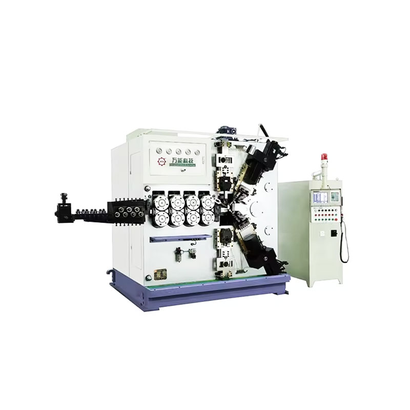
A spring machine is a precision-controlled forming system that takes raw wire from a spool and bends it into a finished spring in a single continuous pass. Modern CNC versions replace the cam-and-lever mechanisms of older machines with servo-driven axes that can be reprogrammed in minutes. Understanding what happens inside the machine is essential for troubleshooting diameter drift, pitch variation, and end-condition defects.
Wire enters through a straightener — a series of rollers set at alternating angles — that removes the natural cast and helix from the spool. Inadequate straightening is the leading cause of coil diameter variation in production. Most spring coiling machines use 5-roller or 9-roller straighteners; heavier wire above 6 mm may use powered pinch-roller feeds with torque feedback. Feed rate directly determines the machine's output speed: at 200 mm/s feed, a 30 mm free-length spring takes about 0.15 seconds to wind.
The coiling point — a hardened carbide pin or roller — deflects the wire against a mandrel or into free air to create the coil diameter. Moving the coiling point inward increases the diameter; outward decreases it. The pitch tool controls the axial advance per revolution, setting the spring's pitch angle and ultimately the free length. On a CNC spring machine, both axes update position 500–1000 times per second, allowing tapered diameters, variable pitch, and barrel-shaped profiles all within the same wind cycle.
Once the programmed number of coils is reached, a cut-off knife severs the wire cleanly. The cut-off must fire at the correct rotational angle to produce consistent end geometry. Poor cut-off timing creates hooks, burrs, or crushed ends that fail grinding or affect spring squareness. High-speed machines use pneumatic or servo cut-off systems with response times under 5 milliseconds.
Leading spring machine manufacturers include WAFIOS (Germany), Itaya (Japan), Bamatec (Switzerland), and numerous Chinese manufacturers. A mid-range 4-axis CNC coiling machine capable of handling 0.3–6 mm wire typically costs between $40,000 and $120,000 USD depending on speed and axis configuration.
The following sequence covers industrial compression spring production from raw wire to finished, inspected part. Torsion and extension springs follow the same skeleton with modifications at the forming and heat treatment stages.
Incoming wire is verified against the material certificate: diameter tolerance (typically ±0.5% for music wire), tensile strength, surface condition, and spool weight. Wire with surface seams, pitting, or diameter out of tolerance is rejected before it reaches the machine. Diameter deviation of just 2% changes spring rate by approximately 8% (since rate scales with d⁴).
The operator loads the wire through the straightener and feeds it to the coiling point. The CNC program specifies: wire feed rate, coil diameter setpoint, pitch per revolution, total coil count, and cut-off position. First-article samples are wound at slow speed — typically 10–20% of production speed — and measured against the print. Adjustments to coiling point position, pitch tool angle, and cut-off timing are made until all dimensions are within tolerance.
Once the first article is approved, the machine runs at full production speed. Output rates vary by wire size: 0.5 mm wire runs at 200–400 springs/minute; 6 mm wire runs at 15–40 springs/minute. In-process samples are pulled every 500–1000 pieces and checked for free length, outer diameter, and total coil count. Automatic vision systems on higher-end machines check every part.
Freshly wound springs carry residual stress from the forming process. Stress relieving removes this without recrystallizing the wire's cold-worked microstructure. For carbon steel springs, this means 200–260 °C for 20–30 minutes in a mesh belt oven or batch oven. Stainless steel requires 315–370 °C. After treatment, free length can change by 0.5–2% as residual stress relaxes — this must be factored into the winding program.
Compression springs with closed ends are ground on a double-disc grinder or a rotary grinder to produce a flat bearing surface. The grind must remove enough material to bring squareness within tolerance — typically less than 1.5° of tilt per the DIN 2096 / ISO 10243 standard. Under-grinding leaves a point contact instead of full bearing contact; over-grinding cuts into the active coils and reduces spring rate.
High-load springs are compressed to solid height one or more times to induce favorable compressive residual stress on the inner coil surface. This process — called scragging or presetting — permanently shortens the spring by 1–5% of free length but increases the spring's resistance to permanent set during service life. Automotive suspension springs and valve springs are almost always scragged before shipment.
Shot peening bombards the spring surface with small steel or ceramic balls at high velocity, creating a compressive stress layer 0.1–0.3 mm deep. This layer resists tensile fatigue cracks from initiating on the wire surface. Shot peening can extend spring fatigue life by 200–500% in high-cycle applications such as engine valve springs that cycle 10⁸ times or more.
Carbon steel springs without a protective coating will rust within weeks in humid environments. Common finishes include: electro-zinc plating (5–12 µm), zinc-phosphate + oil, powder coating, or e-coating. Springs for food, medical, or outdoor environments use stainless steel base material or additional organic coatings. Hydrogen embrittlement from plating is a known risk — post-plate baking at 190–220 °C for 4–8 hours drives off absorbed hydrogen.
Every production lot undergoes dimensional and load testing. A spring rate tester compresses the spring to two or three defined lengths and records force at each point. The measured rate must match the design specification within ±10% for general springs or ±5% for precision springs. Statistical sampling follows AQL tables — typically AQL 1.0 or 1.5 for critical applications — meaning a lot of 1,000 springs requires inspection of 80–125 samples.
For prototyping, repair work, or small quantities, it is entirely possible to make a functional compression or extension spring without a dedicated spring machine. The tooling is minimal and the process is straightforward for wire under 2 mm in diameter.
Hand-wound springs will not match the dimensional consistency of machine-made parts. Expect free length variation of ±3–5% and diameter variation of ±2–4% when winding by hand. For anything requiring tighter tolerances or more than 20–30 pieces, a spring coiling machine is the practical solution.
Even with a well-maintained spring machine, defects appear when setup drifts or material properties vary. The following table maps the most frequent defects to their root causes and corrective actions.
| Defect | Likely Cause | Corrective Action |
|---|---|---|
| OD gradually increases during run | Worn coiling point, wire spool tension decreasing | Replace coiling point; add wire brake tension |
| Free length too short | Pitch tool not advancing far enough; incorrect coil count | Increase pitch tool offset; verify encoder counts |
| Non-square ends | Uneven end coil closure; grinder wheel not flat | Adjust end coil cam; dress grinder wheel |
| Wire surface cracking | Seams in wire; mandrel diameter too small (high stress) | Reject wire lot; increase spring index (D/d ratio) |
| Tangled / interlocked springs | OD too large relative to pitch; end hooks on extension springs | Reduce OD; add dividers in output bin |
| Inconsistent spring rate | Pitch variation; wire diameter outside tolerance | Re-check pitch tool; tighten wire lot specification |
| Burr or sharp cut-off end | Dull cut-off knife; incorrect cut-off angle | Sharpen or replace knife; adjust cut-off cam angle |
Springs are not a commodity part — small dimensional deviations produce significant changes in load and fatigue life. The major standards governing spring tolerances are DIN 2095 / 2096 (compression), DIN 2097 (extension), and DIN 2194 (torsion). ISO 10243 and ISO 8458 also apply to international supply chains.
DIN 2095 defines three tolerance grades: Grade 1 (±0.5% of free length), Grade 2 (±1%), Grade 3 (±2%). A spring machine producing Grade 1 parts on 80 mm free-length springs must hold ±0.4 mm — achievable on a well-tuned CNC coiling machine but not on older cam-type machines.
Tolerances on OD follow the spring index and wire diameter. For a typical spring with OD = 20 mm and d = 1.5 mm, Grade 2 tolerance is approximately ±0.4 mm. Modern spring machine systems with servo feedback hold OD within ±0.1 mm routinely.
Squareness (perpendicularity of the end coil face to the spring axis) is specified as a maximum deviation in mm per 100 mm of free length. DIN 2096 Grade 2 allows 3 mm per 100 mm. Springs for precision assembly — valve springs, instrument springs — require less than 1 mm per 100 mm.
Spring rate is tested on a load cell at two defined lengths. Tolerance is typically ±10% for commercial springs and ±5% for precision springs. Automotive suspension springs are often held to ±3% rate and ±1% free length, requiring 100% testing on automated spring rate machines.
Moving from a hand-wound prototype or a single-shift manual machine to full production requires planning around three variables: machine capacity, material logistics, and inspection infrastructure.
Use the following calculation: if you need 500,000 springs per month and your spring coiling machine runs at 80 springs/minute, you need approximately 104 machine-hours per month. At 22 working days and 8 hours/shift, a single machine on one shift produces 192 machine-hours per month — well within capacity. But when you account for setup time (30–60 minutes per changeover), maintenance downtime (5–8% of total time for a well-maintained machine), and first-article approval time, effective capacity drops to roughly 160–170 usable hours. Plan for 75–80% actual utilization when quoting production capacity.
At 500,000 springs/month with a 30 mm free-length spring using 1.5 mm wire, you consume roughly 15,000 meters of wire per month — about 130–160 kg depending on alloy density. Buying wire in 100 kg spools versus 500 kg coils can cut material cost by 8–15%. Confirm spool compatibility with your spring machine's pay-off system before ordering large quantities.
100% manual inspection at 500,000 pieces per month is not practical. Automated vision systems for spring diameter, free length, and end condition check 60–120 springs per second and flag defects in real time. In-line load testers verify spring rate on every part. The capital cost for a full automated inspection cell runs $25,000–$80,000 USD but pays back quickly when scrap rates drop from 1–2% to under 0.1%.
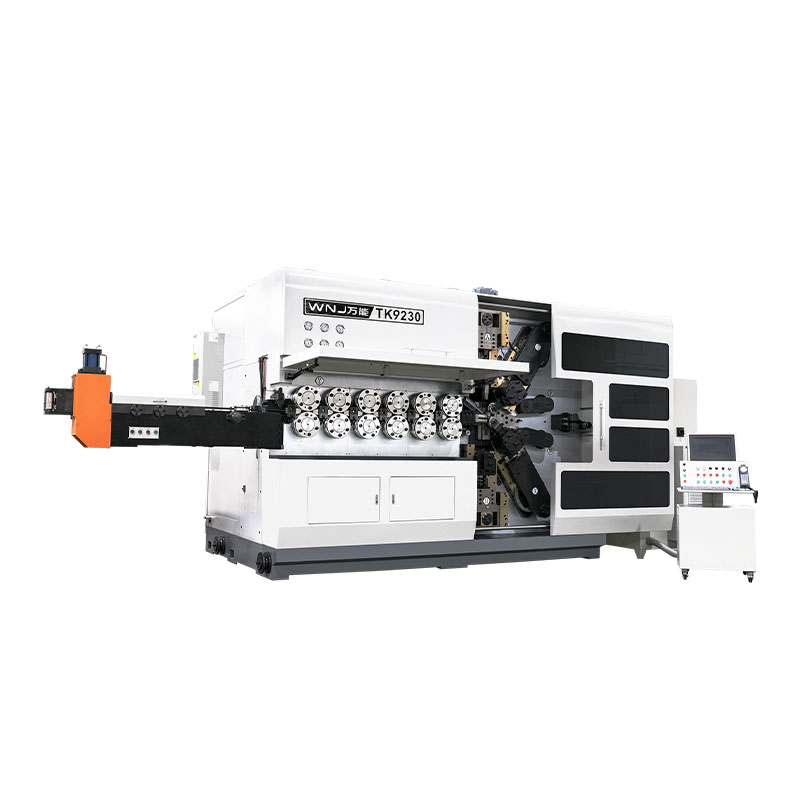
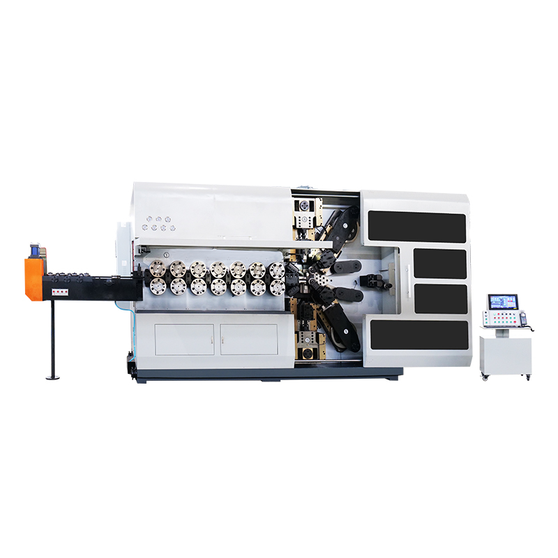
TK-6160 TK-6160 CNC SPRING ROLLING MACHINE...
詳細を見る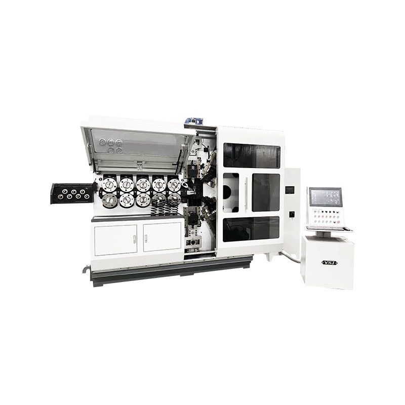
TK-6120 TK-6120 CNC SPRING ROLLING MACHINE...
詳細を見る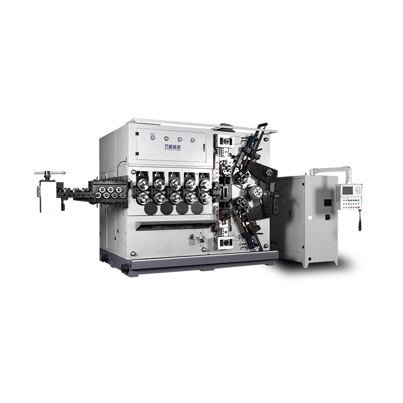
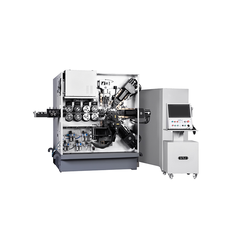
TK-5200 TK-5200 5AXES CNC SPRING COILING MACHINE...
詳細を見る
TK-5160 TK-5160 5AXES CNC SPRING COILING MACHINE...
詳細を見る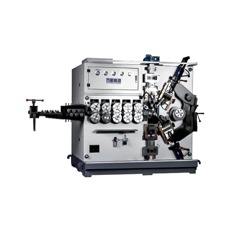
TK-5120 TK-5120 5AXES CNC SPRING COILING MACHINE...
詳細を見る
TK TK 10AXES CNC SPRING SCROLL MACHINE...
詳細を見る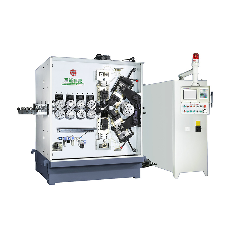
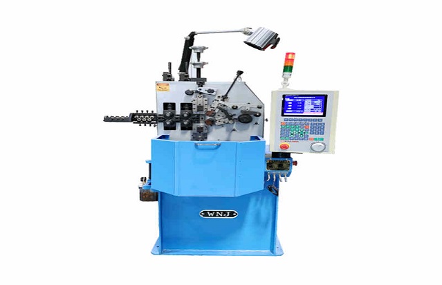
TK-580B、 TK-590 TK-580B、 TK-590 5AXES CNC SPRING COILING MACHINE...
詳細を見る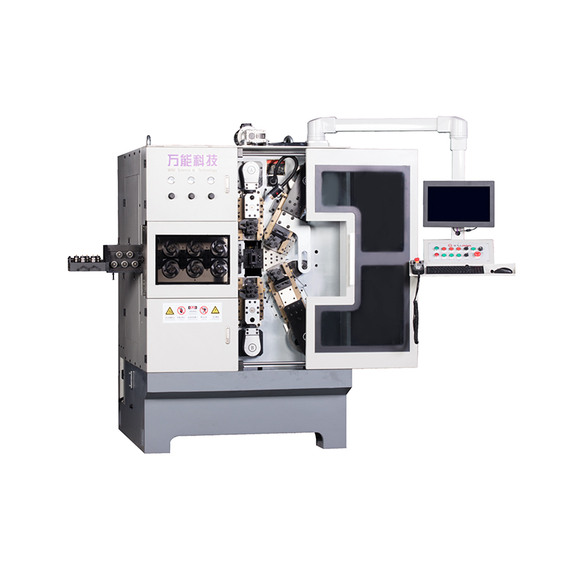
TK-760TK-760 6-7AXES CNC SPRING COILING MACHINE...
詳細を見るMobile QR Code

 Language
  中文简体
中文简体 English
 русский
 Español