Language
Content
Buckling happens when a compression spring is loaded past a point where it can no longer stay straight along its axis, and the coils shift sideways instead of compressing evenly. A spring buckles when its free length is more than roughly 4 times its mean coil diameter and it is not supported by a rod, hole, or fixture. This is a geometry problem before it is a material problem: a slender, unguided spring behaves like a thin column under load, and once the compressive force passes a critical threshold, the spring bows outward rather than compressing in a straight line.
The practical consequence is not academic. A buckled spring rubs against the housing wall, wears unevenly, loses force accuracy, and in many assemblies eventually binds or fractures at the point of contact. Anyone designing with compression springs, or setting up a spring machine to produce them, needs to know where the buckling line sits before the spring ever gets loaded in the field.
Spring engineers use a single ratio to flag buckling risk before any load calculation: the free length divided by the mean coil diameter, written as L / D. This is the same logic used for slender columns in structural engineering, adapted to helical springs.
These figures come from classic spring design references such as the Associated Spring/Barnes Group engineering handbook and are still the baseline most manufacturers design against today. A spring with L / D = 4 and free ends can lose over 60 percent of its theoretical load capacity to buckling before it ever reaches solid height.
The slenderness ratio alone does not tell the whole story. How the two ends of the spring are held changes the critical buckling load dramatically, because fixed ends resist the sideways bowing that free ends cannot.
| End Condition | Description | Relative End Condition Constant |
|---|---|---|
| Both ends fixed against rotation | Ends flat, ground, and squared against rigid plates | 0.5 |
| One fixed, one hinged | Common in one-sided piston or plunger fixtures | 0.707 |
| Both ends hinged (pinned) | Free to rotate but centered at both ends | 1.0 |
| One fixed, one free | Cantilever-style loading, worst case | 2.0 |
A spring fixed at both ends can tolerate roughly four times the deflection of the same spring loaded with one free end before buckling starts. This is why bolted, flat-ground spring ends are specified so often in industrial assemblies: the fixture itself becomes part of the anti-buckling design.
For designers who need an actual number rather than a rule of thumb, the critical deflection ratio (deflection at buckling divided by free length) can be estimated from a standard curve based on L / D and the end condition constant, combined with the spring index and Poisson's ratio of the material. In practice, most manufacturers skip the closed-form calculation and instead pull the ratio from a published buckling chart, then multiply it by the spring's free length to get the actual critical deflection in millimeters or inches.
As a working example: a steel compression spring with a free length of 60 mm and a mean diameter of 12 mm has an L / D of 5.0. With both ends fixed, the critical deflection ratio from a standard chart sits near 0.30, meaning the spring can safely deflect about 18 mm before buckling risk becomes significant. If that same spring only had one end fixed and one end free, the safe deflection would drop to roughly 6 to 8 mm, a difference large enough to fail a design that was never checked against end conditions.
The chart-based method exists because the exact closed-form solution for helical spring buckling involves the spring's effective bending and torsional stiffness, both of which depend on wire diameter, coil diameter, and the shear modulus of the material at the same time. Rather than solving that relationship from scratch for every part, most spring engineers keep a buckling curve on hand, plot L / D on one axis, and read the critical deflection ratio off the corresponding end-condition line. This is faster on the shop floor and repeatable across an engineering team, which matters more in daily practice than shaving decimal points off a theoretical model.
A worked example makes the process concrete. Consider a compression spring intended for a hand-operated valve actuator, with the following starting specification:
Step one is the slenderness ratio: 80 divided by 14 gives an L / D of 5.7, which is already above the 5.3 threshold where buckling is treated as likely rather than possible. Step two is the end condition. Because the spring simply sits between two flat plates with no fixturing, both ends behave as hinged rather than fixed, giving an end condition constant of 1.0, the middle case rather than the best case.
Step three is reading the critical deflection ratio for L / D of 5.7 with pinned ends from a standard buckling chart, which lands close to 0.20. Multiplying that ratio by the 80 mm free length gives a critical deflection of only 16 mm. Since the application calls for 22 mm of working deflection, this spring will buckle before it reaches its intended operating point. The design as specified will fail in service even though the wire diameter and load rating look correct on paper.
Step four is fixing it. Three options solve the problem without changing the spring's force output: add a guide rod through the coil ID sized for about 12 mm outer diameter, which raises the effective critical deflection well above 22 mm; specify closed and ground ends against the plates to move the end condition constant toward 0.5; or split the spring into two 40 mm springs in series with a center guide, which drops the effective L / D of each segment to 2.85, comfortably under the safe threshold with no guide needed at all. This kind of check, done before tooling is cut, is far cheaper than a field failure discovered after thousands of units are in service.
Spring index, the ratio of mean coil diameter to wire diameter, is usually discussed in the context of stress concentration and coiling difficulty, but it also feeds into the buckling calculation because it affects the ratio between a spring's axial stiffness and its bending stiffness. A low-index spring, tightly wound relative to its wire size, behaves stiffer in bending relative to its axial rate, which modestly improves buckling resistance compared to a high-index spring of the same L / D.
In practical terms this is a secondary effect. A spring index change from 6 to 10 shifts the critical deflection ratio by only a few percentage points, far less than the swing caused by end condition or slenderness ratio. Designers should not rely on tightening the spring index as a substitute for guiding a spring that is already past the safe L / D threshold, but it is worth knowing as a secondary lever when a design sits close to the boundary and a small margin is all that is needed.
Spring index also has a practical coiling implication that circles back to buckling control. Very low index springs, below about 4, are harder to coil consistently on a spring machine and are more prone to coil diameter variation, which can undo any theoretical buckling benefit through part-to-part inconsistency. Very high index springs, above about 12, coil more easily but are inherently more flexible in bending, which works against buckling resistance. Most industrial compression spring designs settle in the 5 to 9 index range partly for this reason, balancing coiling consistency against buckling and stress performance together.
Everything discussed so far assumes a static or slowly applied load, which is how buckling charts are built. Real assemblies often load a spring cyclically, and dynamic conditions change the picture in ways that static charts do not capture directly.
Three dynamic effects matter in practice. First, a spring operating close to its static buckling threshold can buckle intermittently under cyclic load even if it passes a static check, because momentary side loads from vibration, misalignment, or impact can push a marginal spring past the threshold for a fraction of a cycle. Second, repeated buckling events concentrate bending stress at the point of maximum lateral deflection, which accelerates fatigue cracking at that location rather than distributing stress evenly around the coil as a properly axial spring would. Third, resonance matters separately from buckling: if the operating frequency approaches the spring's natural surge frequency, coils can bounce out of phase with each other, which looks similar to buckling from the outside but is a different failure mode with a different fix, typically damping or a change in wire diameter rather than guiding.
The practical guidance for cyclic applications is to design with extra margin below the static buckling threshold rather than designing to the line. A common industrial practice is to keep working deflection at or below 80 percent of the calculated critical deflection for any spring that will see more than a few hundred load cycles, which absorbs the added risk from dynamic side loading without requiring a full dynamic buckling analysis on every part.
Buckling is not evenly distributed across applications. It concentrates wherever long, unguided springs are combined with tight packaging or high-deflection requirements.
| Application Area | Typical Buckling Driver | Common Mitigation |
|---|---|---|
| Automotive suspension and clutch assemblies | Long travel required in a narrow bore | Guide sleeve integrated into the housing bore |
| Industrial valve actuators | High force needs a longer spring at a fixed diameter | Center guide rod plus closed and ground ends |
| Handheld tools and switches | Very slim housings limit coil diameter | Two shorter springs in series with a center washer |
| Packaging and dispensing machinery | High-cycle operation amplifies marginal designs | Extra deflection margin below the static buckling limit |
| Furniture and mechanical hardware | Cost pressure discourages guide rods | Lower L / D by widening coil diameter within the available space |
The common thread across all five categories is packaging pressure. Buckling risk rarely comes from a designer choosing a bad spring; it comes from a housing, bore, or footprint that forces a longer, thinner spring than the ideal L / D would suggest, which is exactly why guide rods, sleeves, and split-spring arrangements exist as standard solutions rather than exceptions.
Not every spring machine holds the same tolerance band, and the gap matters more for buckling-sensitive designs than for simple, low-slenderness springs where a wider tolerance has little effect.
| Spring Machine Type | Typical Coil Diameter Control | Best Fit for Buckling-Sensitive Parts |
|---|---|---|
| Mechanical cam-driven spring machine | Wider batch-to-batch variation, tooling-dependent | Low L / D parts where buckling margin is generous |
| CNC spring coiling machine, open-loop | Improved repeatability, some drift over long runs | Moderate L / D parts with a guide rod as backup |
| CNC spring machine with closed-loop wire feed and inline gauging | Tight, continuously corrected tolerance through the run | High L / D or tightly guided parts where clearance is small |
| Automated end-grinding cell paired with a spring machine | Controls end squareness directly rather than coil diameter | Any design relying on fixed or near-fixed end conditions |
The takeaway for anyone specifying a buckling-sensitive spring is to match the tolerance capability of the spring machine to how close the design sits to its buckling threshold. A design with generous margin below the critical deflection can tolerate the wider variation of an older mechanical spring machine. A design that depends on a tight guide clearance or a near-fixed end condition needs the tighter, gauged output of a closed-loop CNC spring machine, because even small coil diameter drift can close the guide clearance or shift the effective end condition enough to trigger buckling in a fraction of the batch.
Beyond the core rules already covered, several less obvious mistakes show up repeatedly in field failure reviews.
Most buckling failures in production assemblies trace back to a handful of avoidable design choices. The following rules are used across industrial spring design to keep a compression spring stable through its full working stroke.
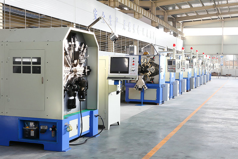
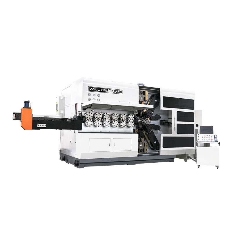
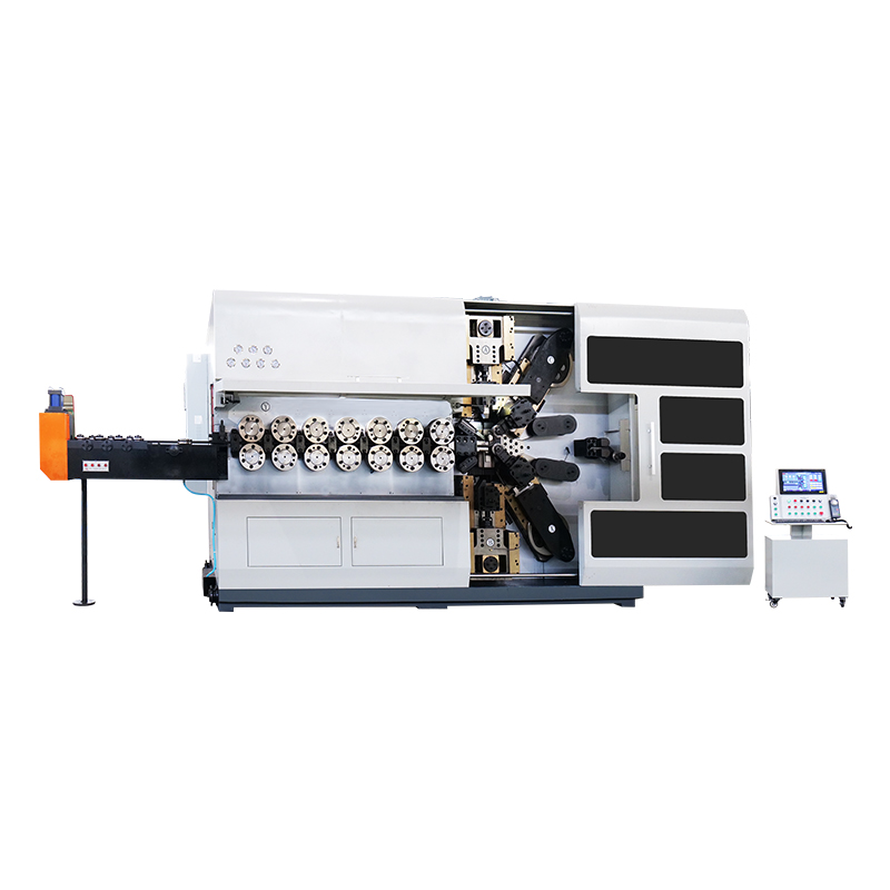
Buckling resistance is decided on the design drawing, but it is only realized if the spring is actually coiled to that geometry. This is where the spring machine used in production plays a direct role. A CNC spring machine that holds tight tolerances on pitch consistency, coil diameter, and squareness of the ground ends produces springs that behave much closer to the calculated buckling threshold than springs coiled on loosely maintained equipment.
Three tolerances in particular matter for buckling behavior:
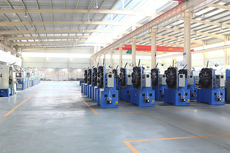
A modern CNC spring coiling machine with closed-loop wire feed control and automated end-grinding can hold coil diameter tolerances within a few hundredths of a millimeter, which is tight enough that the physical spring matches the buckling chart used at the design stage. Springs coiled on older mechanical spring machines without that feedback control tend to show more part-to-part variation, which is one reason buckling complaints sometimes appear inconsistently across a production batch rather than on every unit.
Material affects buckling indirectly, through Poisson's ratio and the shear modulus used in the buckling chart, but the effect is small compared to geometry and end conditions. Switching from music wire to stainless steel 302 changes the critical buckling deflection by only a few percent for the same geometry, because both materials have similar Poisson's ratios in the 0.28 to 0.30 range. The far bigger levers remain slenderness ratio, end fixity, and load alignment. Material selection still matters for fatigue life, corrosion resistance, and temperature performance, but it should not be treated as a buckling fix on its own.
Buckling is not always obvious from the outside, especially in an enclosed housing. Common field signs include:
| Observed Symptom | Likely Cause |
|---|---|
| Scoring or bright wear marks on the inside of the housing bore | Spring is bowing sideways and contacting the wall under load |
| Inconsistent force readings at the same compressed height across units | Some units have crossed the buckling threshold while others have not |
| Audible rattling or a change in sound during actuation | Coils are contacting the housing or a guide rod intermittently |
| Premature fatigue cracking at one localized coil rather than distributed wear | Repeated side-loading from buckling concentrates stress at one point |
If any of these symptoms appear, the fastest diagnostic step is to measure the free length and mean diameter of the actual part and recalculate L / D, rather than assuming the original design number still applies. Tooling wear on a spring machine over time can gradually drift coil diameter outside the original tolerance band, which is worth checking if buckling complaints start appearing on a spring that performed correctly for years.
Divide the free length by the mean coil diameter. If the result is under 4, buckling is unlikely to be a problem in most fixtures. If it is over 4, plan for a guide rod, guide sleeve, or fixed end conditions.
Yes. Buckling is governed by deflection and slenderness, not by whether the spring has reached its stated load rating. A slender, unguided spring can buckle at 40 to 60 percent of its rated deflection.
A properly sized guide rod solves the majority of buckling cases, but it needs enough clearance to avoid binding against the coil ID under lateral load, and it needs to be long enough to support the spring through its full compressed stroke, not just at free length.
Buckling as described here is specific to compression springs. Extension springs are loaded in tension and do not buckle in the same way, and torsion springs fail through different mechanisms related to bending stress at the coil body and legs rather than lateral instability.
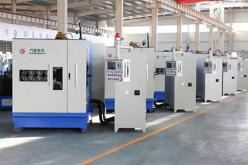
Small variations in free length, coil diameter, or end squareness from the coiling process can shift the actual L / D and end condition just enough to move one part closer to the buckling threshold than another. This is why tolerance control on the spring machine used for production is treated as part of the buckling design, not a separate quality issue.
Before. Checking the slenderness ratio and end condition constant at the drawing stage is far cheaper than discovering buckling after tooling and a spring machine setup are already committed to a production run.
No. Spring index has a real but secondary effect on buckling resistance, typically shifting the critical deflection by only a small percentage. Slenderness ratio and end condition remain the two factors that decide whether a spring buckles.
A common approach is to keep working deflection at or below about 80 percent of the calculated critical deflection for any spring seeing regular cyclic loading, since momentary side loads and vibration can push a marginal design past the static threshold intermittently.
Yes. A static check confirms the spring will not buckle under a slowly applied load, but repeated cycling introduces vibration, momentary misalignment, and surge effects that a static calculation does not account for, which is why extra deflection margin is recommended for cyclic parts.
No. Resonance, sometimes called spring surge, happens when the operating frequency approaches the spring's natural frequency and coils oscillate out of phase with each other. It can look similar to buckling in terms of erratic force output, but it is addressed through damping or a wire diameter change rather than through guiding.
Yes. Load and deflection ratings depend on wire diameter, coil diameter, and active coil count together, so two springs can match on paper while having different free lengths or mean diameters, which changes the slenderness ratio and therefore the buckling threshold for each part.
Active coil count affects the spring rate and therefore the free length needed to deliver a given load, which indirectly changes the slenderness ratio. It does not enter the buckling chart as a separate variable the way free length, mean diameter, and end condition do.
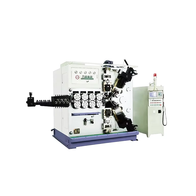
TK-6160 TK-6160 CNC SPRING ROLLING MACHINE...
See Details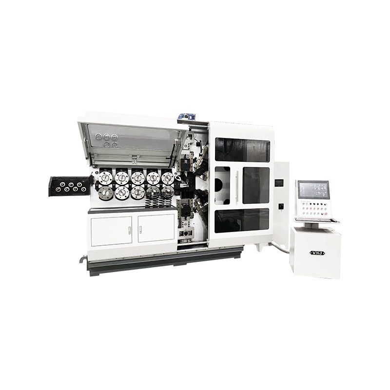
TK-6120 TK-6120 CNC SPRING ROLLING MACHINE...
See Details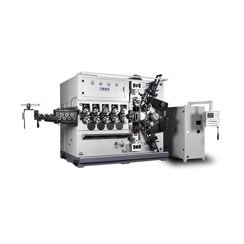
TK-5200 TK-5200 5AXES CNC SPRING COILING MACHINE...
See Details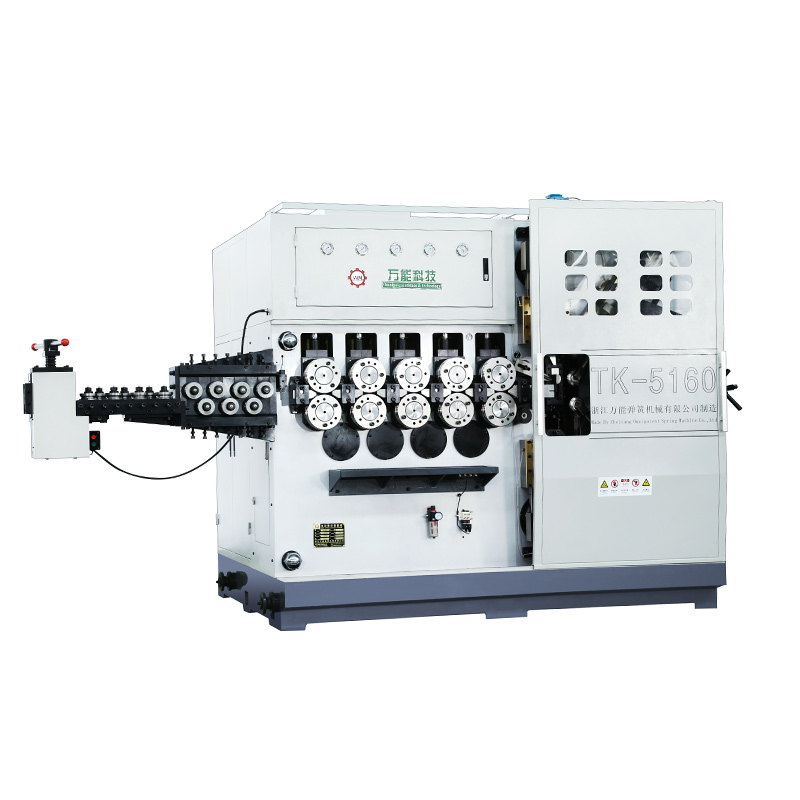
TK-5160 TK-5160 5AXES CNC SPRING COILING MACHINE...
See Details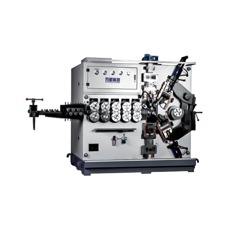
TK-5120 TK-5120 5AXES CNC SPRING COILING MACHINE...
See Details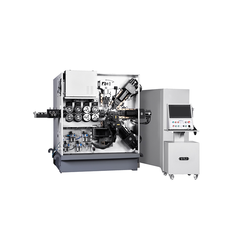
TK TK 10AXES CNC SPRING SCROLL MACHINE...
See Details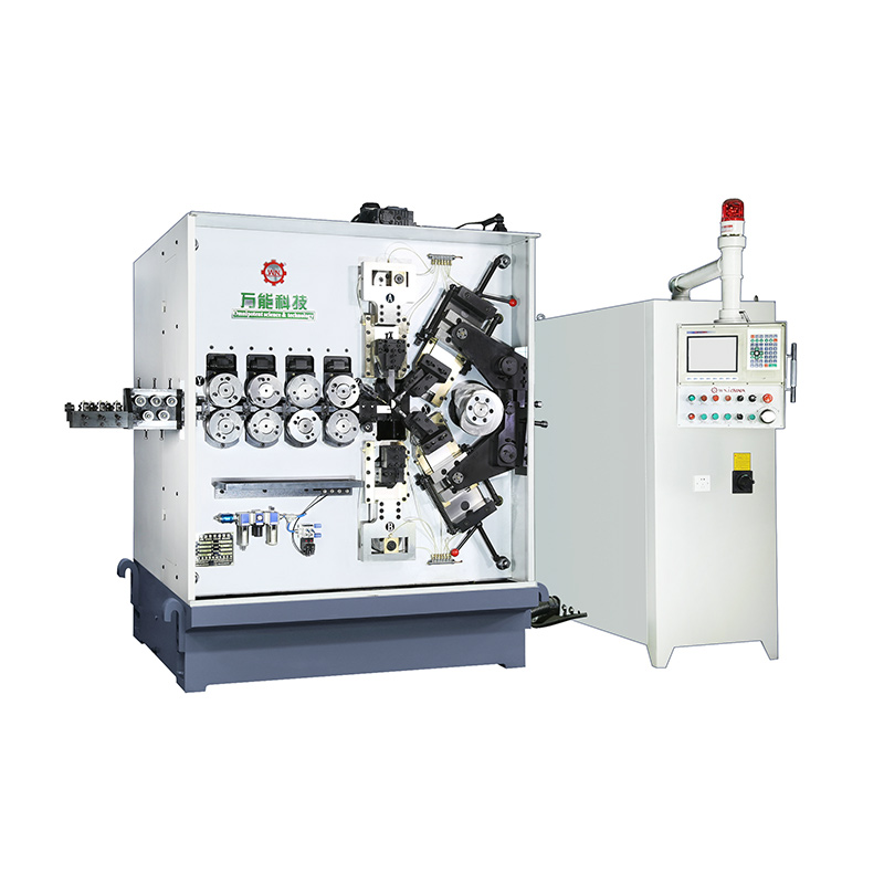
TK-580B、 TK-590 TK-580B、 TK-590 5AXES CNC SPRING COILING MACHINE...
See Details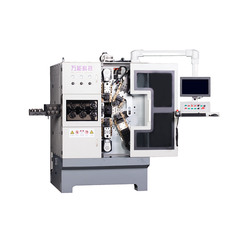
TK-760TK-760 6-7AXES CNC SPRING COILING MACHINE...
See DetailsMobile QR Code

 中文简体
中文简体 English
 русский
 Español